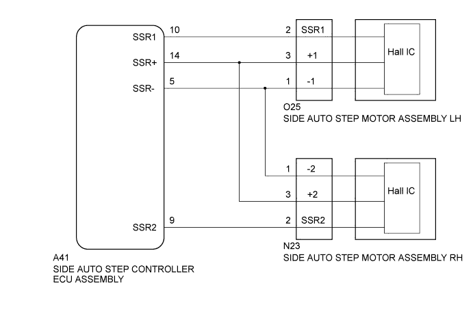
DTC 32 Short to Battery in Hall Effect Sensor Power Circuit |
| DTC No. | Detection Condition | Trouble Area |
| 32 | The side auto step motor hall sensor voltage is more than 4 V when the automatic running board is not in operation. |
|
| 1.CHECK HARNESS AND CONNECTOR (SIDE AUTO STEP MOTOR POWER SOURCE) |
Disconnect the O25*1 and N23*2 side auto step motor assembly connector.
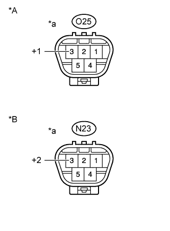 |
Measure the voltage according to the value(s) in the table below.
| Tester Connection | Condition | Specified Condition |
| O25-3 (+1) - Body Ground | When the automatic running board LH is not in operation. | Below 4 V |
| Tester Connection | Condition | Specified Condition |
| N23-3 (+2) - Body Ground | When the automatic running board RH is not in operation. | Below 4 V |
| *A | for LH |
| *B | for RH |
| *a | Front view of wire harness connector (to Side Auto Step Motor Assembly) |
|
| ||||
| OK | ||
 | ||
| ||
| 2.CHECK HARNESS AND CONNECTOR (SIDE AUTO STEP MOTOR - SIDE AUTO STEP CONTROLLER ECU) |
Disconnect the A41 side auto step controller ECU assembly connector.
Measure the voltage according to the value(s) in the table below.
| Tester Connection | Condition | Specified Condition |
| A41-14 (SSR+) - Body Ground | Always | Below 4 V |
|
| ||||
| OK | ||
| ||
| ||

