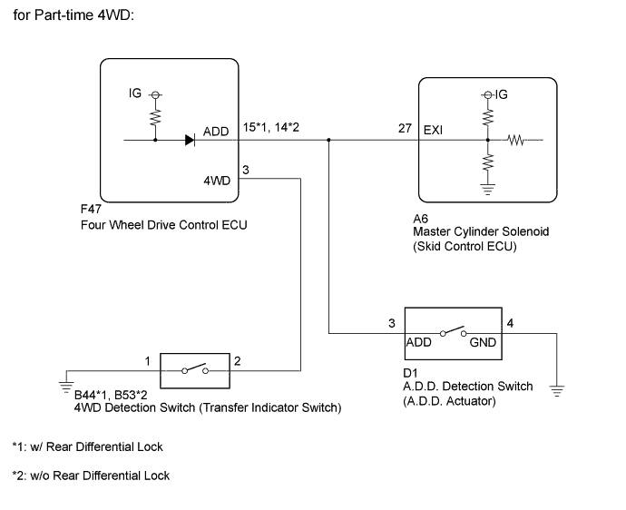
DTC C1282 Center Differential Lock Position Switch |
| DTC Code | DTC Detection Condition | Trouble Area |
| C1282 | Stored during test mode. |
|
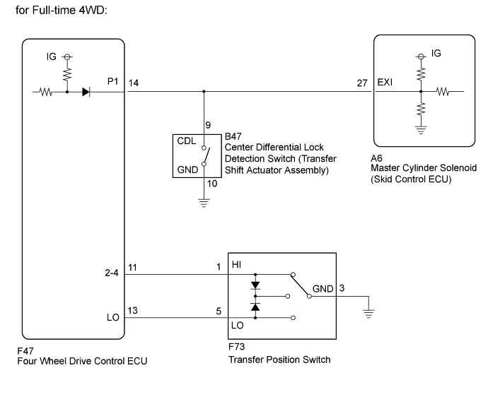
| 1.CONFIRM VEHICLE SPECIFICATIONS |
Confirm the vehicle specifications.
| Result | Proceed to |
| for Part-time 4WD | A |
| for Full-time 4WD | B |
|
| ||||
| A | |
 |
| 2.CHECK TERMINAL VOLTAGE (EXI) |
Disconnect the A6 skid control ECU connector.
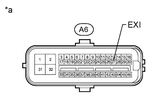 |
Measure the voltage according to the value(s) in the table below.
| Tester Connection | Switch Condition | Specified Condition |
| A6-27 (EXI) - Body ground |
| 11 to 14 V |
| Below 1.5 V |
| *a | Front view of wire harness connector (to Skid Control ECU) |
|
| ||||
| OK | |
|
| 3.CHECK TEST MODE DTC |
Switch the vehicle to test mode, perform the 4WD detection switch signal check, and then check that DTC C1282 is cleared (Click here).
| Result | Proceed to |
| DTC is not cleared | A |
| DTC is cleared | B |
|
| ||||
| A | ||
 | ||
| ||
| 4.CHECK HARNESS AND CONNECTOR (SKID CONTROL ECU - FOUR WHEEL DRIVE CONTROL ECU AND A.D.D. ACTUATOR) |
Disconnect the A6 skid control ECU connector.
Disconnect the F47 four wheel drive control ECU connector.
Disconnect the D1 A.D.D. actuator connector.
Measure the resistance according to the value(s) in the table below.
| Tester Connection | Condition | Specified Condition |
| A6-27 (EXI) - F47-15 (ADD) | Always | Below 1 Ω |
| A6-27 (EXI) - D1-3 (ADD) | Always | Below 1 Ω |
| A6-27 (EXI) - Body ground | Always | 10 kΩ or higher |
| Tester Connection | Condition | Specified Condition |
| A6-27 (EXI) - F47-14 (ADD) | Always | Below 1 Ω |
| A6-27 (EXI) - D1-3 (ADD) | Always | Below 1 Ω |
| A6-27 (EXI) - Body ground | Always | 10 kΩ or higher |
|
| ||||
| OK | ||
| ||
| ||
| 5.CHECK TERMINAL VOLTAGE (EXI) |
Disconnect the A6 skid control ECU connector.
|
Measure the voltage according to the value(s) in the table below.
| Tester Connection | Switch Condition | Specified Condition |
| A6-27 (EXI) - Body ground |
| 11 to 14 V |
| Below 1.5 V |
| *a | Front view of wire harness connector (to Skid Control ECU) |
|
| ||||
| OK | |
|
| 6.CHECK TEST MODE DTC |
Switch the vehicle to test mode, perform the center differential lock detection signal check, and then check that DTC C1282 is cleared (Click here).
| Result | Proceed to |
| DTC is not cleared | A |
| DTC is cleared | B |
|
| ||||
| A | ||
| ||
| ||
| 7.CHECK HARNESS AND CONNECTOR (SKID CONTROL ECU - FOUR WHEEL DRIVE CONTROL ECU AND TRANSFER SHIFT ACTUATOR ASSEMBLY) |
Disconnect the A6 skid control ECU connector.
Disconnect the F47 four wheel drive control ECU connector.
Disconnect the B47 transfer shift actuator assembly connector.
Measure the resistance according to the value(s) in the table below.
| Tester Connection | Condition | Specified Condition |
| A6-27 (EXI) - F47-14 (P1) | Always | Below 1 Ω |
| A6-27 (EXI) - B47-9 (CDL) | Always | Below 1 Ω |
| A6-27 (EXI) - Body ground | Always | 10 kΩ or higher |
|
| ||||
| OK | ||
| ||
| ||

