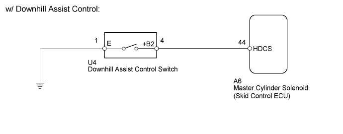
DTC C1379 Downhill Assist Control Switch Malfunction (Test Mode DTC) |
| DTC Code | DTC Detection Condition | Trouble Area |
| C1379 | Stored only during test mode. |
|
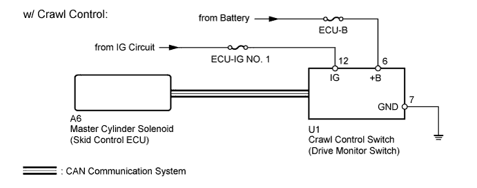
| 1.CONFIRM VEHICLE SPECIFICATIONS |
Confirm the vehicle specifications.
| Result | Proceed to |
| w/ Downhill Assist Control | A |
| w/ Crawl Control | B |
|
| ||||
| A | |
 |
| 2.READ VALUE USING TECHSTREAM (DOWNHILL ASSIST CONTROL SW) |
Turn the ignition switch off.
Connect the Techstream to the DLC3.
Turn the ignition switch to ON.
Turn the Techstream on.
Enter the following menus: Chassis / ABS/VSC/TRAC / Data List.
Check the Data List for proper functioning of the downhill assist control switch.
| Tester Display | Measurement Item/Range | Normal Condition | Diagnostic Note |
| Downhill Assist Control SW | Downhill assist control switch / ON or OFF | ON: Downhill assist control on OFF: Downhill assist control off | - |
|
| ||||
| OK | |
|
| 3.CHECK TEST MODE DTC |
Perform the Downhill Assist Control Switch Check in the Test Mode Procedure (Click here).
|
| ||||
| OK | ||
 | ||
| ||
| 4.INSPECT DOWNHILL ASSIST CONTROL SWITCH |
Remove the downhill assist control switch (Click here).
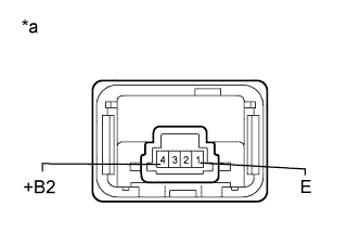 |
Measure the resistance according to the value(s) in the table below.
| Tester Connection | Switch Condition | Specified Condition |
| 1 (E) - 4 (+B2) | Not pushed in | 10 kΩ or higher |
| Pushed in | Below 1 Ω |
| *a | Component without harness connected (Downhill Assist Control Switch) |
|
| ||||
| OK | |
|
| 5.CHECK HARNESS AND CONNECTOR (SKID CONTROL ECU - DOWNHILL ASSIST CONTROL SWITCH/BODY GROUND) |
Disconnect the A6 skid control ECU connector.
Disconnect the U4 downhill assist control switch connector.
Measure the resistance according to the value(s) in the table below.
| Tester Connection | Condition | Specified Condition |
| A6-44 (HDCS) - U4-4 (+B2) | Always | Below 1 Ω |
| A6-44 (HDCS) - Body ground | Always | 10 kΩ or higher |
| U4-1 (E) - Body ground | Always | Below 1 Ω |
|
| ||||
| OK | ||
| ||
| ||
| 6.CHECK CAN BUS |
Check that there are no problems with the CAN communication system (Click here).
|
| ||||
| OK | |
|
| 7.READ VALUE USING TECHSTREAM (CRAWL CONTROL MODE SELECT SWITCH) |
Turn the ignition switch off.
Connect the Techstream to the DLC3.
Turn the ignition switch to ON.
Turn the Techstream on.
Enter the following menus: Body Electrical / D-SEAT SW / Data List.
Check the Data List for proper functioning of the crawl control mode select switch.
| Tester Display | Measurement Item/Range | Normal Condition | Diagnostic Note |
| Crawl Control Main Switch | Crawl control switch (ON/OFF switch)/ ON or OFF | ON: Crawl control on OFF: Crawl control off | - |
|
| ||||
| OK | |
|
| 8.READ VALUE USING TECHSTREAM (CRAWL CONTROL SWITCH) |
Turn the ignition switch off.
Connect the Techstream to the DLC3.
Turn the ignition switch to ON.
Turn the Techstream on.
Enter the following menus: Chassis / ABS/VSC/TRAC / Data List.
Check the Data List for proper functioning of the crawl control switch.
| Tester Display | Measurement Item/Range | Normal Condition | Diagnostic Note |
| Crawl Control Switch | Crawl switch (mode select switch)/ LOW, MIDLOW, MID, MIDHIGH or HIGH | Actual crawl speed selector switch position | - |
|
| ||||
| OK | |
|
| 9.CHECK TEST MODE DTC |
Perform the crawl switch check in the Test Mode Procedure (Click here).
|
| ||||
| OK | ||
| ||
| ||
| 10.CHECK TERMINAL VOLTAGE AND RESISTANCE (IG, +B, GND) |
Disconnect the U1 drive monitor switch connector.
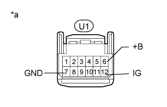 |
Measure the voltage according to the value(s) in the table below.
| Tester Connection | Switch Condition | Specified Condition |
| U1-6 (+B) - Body ground | Always | 11 to 14 V |
| U1-12 (IG) - Body ground | Ignition switch ON | 11 to 14 V |
Measure the resistance according to the value(s) in the table below.
| Tester Connection | Condition | Specified Condition |
| U1-7 (GND) - Body ground | Always | Below 1 Ω |
| *a | Front view of wire harness connector (to Drive Monitor Switch) |
|
| ||||
| OK | ||
| ||
| ||
| 11.REPLACE DRIVE MONITOR SWITCH |
Replace the drive monitor switch (Click here).
| NEXT | |
|
| 12.CHECK TEST MODE DTC |
Perform the crawl switch check in the Test Mode Procedure (Click here).
|
| ||||
| OK | ||
| ||
| ||

