If there are gaps at positions shown in the illustration, fill up with seal packing by using a sealer gun.
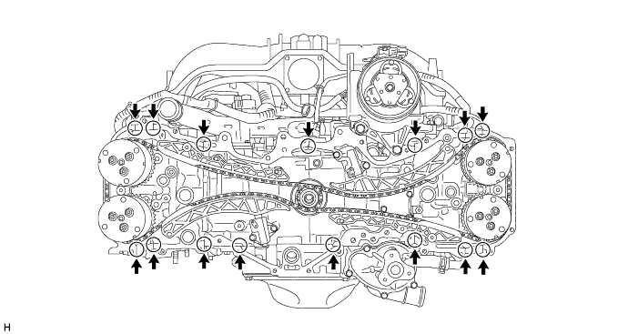
- Seal packing:
- Three Bond 1217G, 1217H or equivalent
OIL PUMP > INSTALLATION |
| 1. INSTALL TIMING CHAIN OR BELT COVER SUB-ASSEMBLY |
Apply a light coat of engine oil to the 4 O-rings.
Remove any old packing material remaining on the sealing surfaces before applying seal packing.
If there are gaps at positions shown in the illustration, fill up with seal packing by using a sealer gun.
Using a sealer gun, apply seal packing in a continuous line to the timing chain cover as shown in the following illustration.
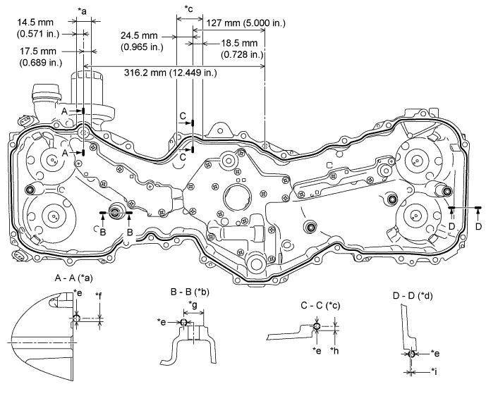
| *a | Range A | *b | Boss (5 locations) |
| *c | Range B | *d | Other than ranges A and B |
| *e | φ3.5 to 4.5 mm (0.138 to 0.177 in.) | *f | 2 mm (0.079 in.) |
| *g | φ12 mm (0.472 in.) | *h | 2.5 mm (0.098 in.) |
| *i | 0.5 mm (0.020 in.) | - | - |
Temporarily tighten the timing chain cover with the 32 bolts.
Fully tighten the 32 bolts shown in the illustration.
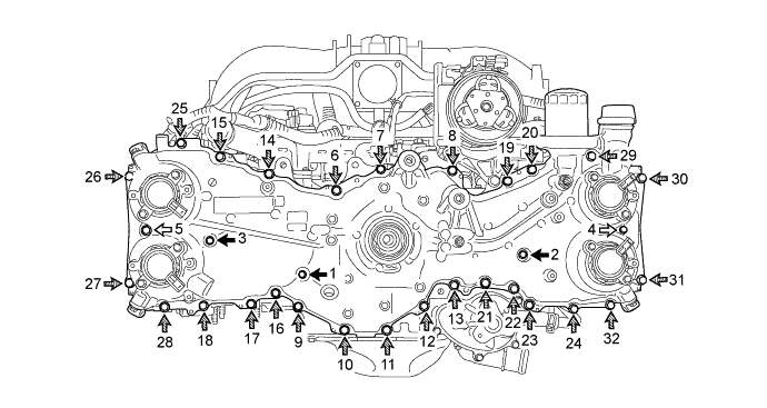
 | Bolt A |  | Bolt B |
 | Bolt C |  | Bolt D |
| Item | Length | Item | Length |
| Bolt A | 20 mm (0.787 in.) | Bolt B | 50 mm (1.969 in.) |
| Bolt C | 25 mm (0.984 in.) | Bolt D | 60 mm (2.362 in.) |
| 2. INSTALL TIMING CHAIN OR BELT COVER OIL SEAL |
Apply engine oil to the lip of a new timing chain or belt cover oil seal.
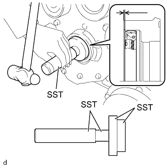 |
Using SST and a hammer, tap in the timing chain or belt cover oil seal until its surface is flush with the timing chain cover edge.
| 3. INSTALL NO. 1 IDLER PULLEY SUB-ASSEMBLY |
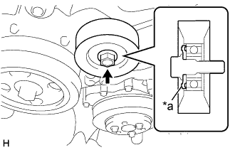 |
Install the washer plate to the No. 1 idler pulley sub-assembly as shown in the illustration.
| *a | Protrusion |
Install the washer plate and No. 1 idler pulley sub-assembly with the bolt.
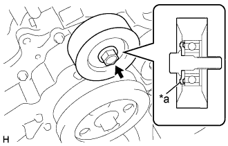 |
Install the washer plate to the No. 1 idler pulley sub-assembly as shown in the illustration.
| *a | Protrusion |
Install the washer plate and No. 1 idler pulley sub-assembly with the bolt.
| 4. INSTALL V-RIBBED BELT TENSIONER ASSEMBLY |
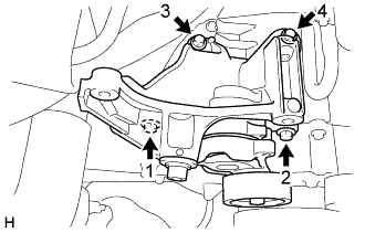 |
Temporarily install the V-ribbed belt tensioner with the 5 bolts.
Tighten the 4 bolts in the order shown in the illustration.
| 5. INSTALL NO. 2 IDLER PULLEY SUB-ASSEMBLY |
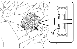 |
Install the washer plate to the No. 2 idler pulley sub-assembly as shown in the illustration.
| *a | Protrusion |
Install the washer plate and No. 2 idler pulley sub-assembly with the bolt.
| 6. INSTALL OIL LEVEL DIPSTICK GUIDE |
Install a new O-ring to the oil level dipstick guide.
Apply a light coat of engine oil to the O-ring.
Install the oil level dipstick guide with the bolt.
Install the oil level dipstick sub-assembly.
| 7. CONNECT ENGINE WIRE |
Connect the camshaft position sensor connector and camshaft timing oil control valve connector.
Engage the wire harness clamp.
Connect the engine oil pressure switch connector and engine oil temperature sensor connector.
Connect the camshaft position sensor connector and camshaft timing oil control valve connector.
Connect the 2 camshaft position sensor connectors and camshaft timing oil control valve connector.
Connect the camshaft position sensor connector.
Install the wire harness bracket with the bolt.
Engage the wire harness clamp.
Install the 2 wire harness brackets with the 2 bolts.
| 8. INSTALL INJECTOR COVER (for Bank 1) |
Install the injector cover (for bank 1) to the intake manifold with the 2 bolts.
Engage the 4 clamps to install the wire harness to the injector cover (for bank 1).
| 9. INSTALL CRANKSHAFT PULLEY |
Install the crankshaft pulley spacer.
Install a new O-ring to the crankshaft pulley spacer.
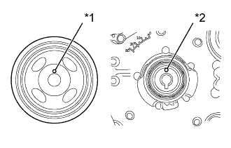 |
Install the crankshaft pulley while aligning the knock hole of the pulley with the knock pin on the crankshaft pulley spacer.
| *1 | Knock Hole |
| *2 | Knock Pin |
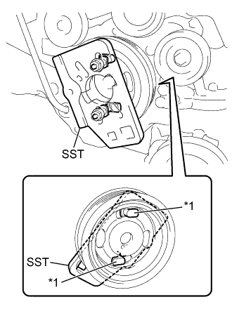 |
Install SST to the crankshaft pulley.
| *1 | Claw |
Apply engine oil to the crankshaft pulley set bolt.
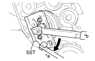 |
Using SST, hold the crankshaft pulley and tighten the crankshaft pulley set bolt.
| *a | Hold |
| *b | Turn |
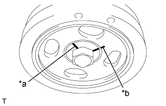 |
Using a marker, draw the reference line (A) on the crankshaft pulley set bolt and also the reference line (B) on the crankshaft pulley according to the line engraved around the crankshaft pulley set bolt head as shown in the illustration.
| *a | Reference Line A |
| *b | Reference Line B |
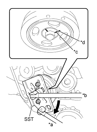 |
Using SST, hold the crankshaft pulley, and tighten the crankshaft pulley set bolt by 90° until the reference lines A and B are aligned.
| *a | Hold |
| *b | Turn |
| *c | Reference Line A |
| *d | Reference Line B |
| 10. INSTALL WATER PUMP PULLEY |
Temporarily install the water pump pulley with the 3 bolts.
Using SST, hold the water pump pulley and tighten the 3 bolts.
| 11. CONNECT RADIATOR OUTLET HOSE |
Install the clamp and connect the radiator outlet hose.
| 12. INSTALL EXHAUST MANIFOLD |
| 13. INSTALL WATER FILLER SUB-ASSEMBLY |
Install the 2 clamps and connect the water filler sub-assembly.
Install the water filler sub-assembly with 2 bolts.
| 14. INSTALL RADIATOR RESERVE TANK ASSEMBLY |
Install the radiator reserve tank assembly with the 2 bolts.
| 15. INSTALL INJECTOR DRIVER |
Install the injector driver with the 3 bolts.
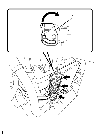 |
Connect the 4 connectors to the injector driver. Move the lock levers in the direction indicated by the arrow to lock the 3 connectors.
| *1 | Lock Lever |
| Lock with Connector |
| Normal Connector |
| 16. INSTALL GENERATOR ASSEMBLY |
| 17. ADD ENGINE COOLANT |
| 18. ADD ENGINE OIL |
Add new engine oil and install the oil filler cap.
| Oil Grade | Oil Viscosity (SAE) |
|
|
| Item | Capacity |
| Drain and refill with oil filter change | 5.4 liters (5.7 US qts, 4.8 Imp. qts) |
| Drain and refill without oil filter change | 5.2 liters (5.5 US qts, 4.6 Imp. qts) |
| Dry fill | 6.3 liters (6.7 US qts, 5.5 Imp. qts) |
| 19. INSPECT FOR ENGINE OIL LEAK |
Start the engine. Make sure that there are no oil leaks from the connection point of the oil filter sub-assembly.
| 20. CHECK ENGINE OIL LEVEL |
Park the vehicle in a level place.
With the engine turned off, check that the engine oil level is between the full level and low level marks.
If low, check for leakage and add oil up to the full level mark.