 |
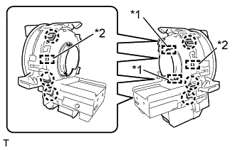
Align the 2 pins and 2 guides, and engage the 6 claws to install the steering sensor to the spiral cable sub-assembly.
| *1 | Guide |
| *2 | Pin |
- NOTICE:
- Do not rotate the spiral cable until the steering sensor has been attached to it.
STEERING ANGLE SENSOR > INSTALLATION |
| 1. INSTALL STEERING SENSOR |
|
Align the 2 pins and 2 guides, and engage the 6 claws to install the steering sensor to the spiral cable sub-assembly.
| *1 | Guide |
| *2 | Pin |
| 2. ALIGN FRONT WHEELS TO FACE STRAIGHT AHEAD |
| 3. INSTALL SPIRAL CABLE WITH SENSOR SUB-ASSEMBLY |
Check that the ignition switch is off.
Check that the cable is disconnected from the negative (-) battery terminal.
Check that the front wheels are facing straight ahead.
Set the turn signal switch to the neutral position.
Engage the 3 claws to install the spiral cable with sensor sub-assembly.
Connect the each connector.
| 4. INSTALL UPPER STEERING COLUMN COVER |
Engage the 2 claws to install the upper steering column cover.
| 5. INSTALL LOWER STEERING COLUMN COVER |
w/ Knee Airbag
Engage the 4 claws to install the lower steering column cover.
Install the 2 screws.
w/o Knee Airbag
Engage the 6 claws to install the lower steering column cover.
Install the 2 screws.
| 6. INSTALL STEERING COLUMN COVER SUPPORT (w/ Entry and Start System) |
Engage the 4 claws and install the steering column cover support.
| 7. INSTALL UPPER INSTRUMENT PANEL METER ORNAMENT |
Connect the connector.
Engage the 2 claws that are holding the upper instrument panel meter ornament and steering column cover together.
Engage the 2 clips and 6 claws.
Install the upper instrument panel meter ornament with the screw.
| 8. INSTALL METER HOOD SUB-ASSEMBLY |
Engage the 12 claws.
Install the meter hood sub-assembly with the screw.
| 9. INSTALL CENTER INSTRUMENT CLUSTER FINISH PANEL SUB-ASSEMBLY |
Engage the 4 clips and 2 claws to install the center instrument cluster finish panel sub-assembly.
| 10. INSTALL LOWER NO. 1 INSTRUMENT PANEL AIRBAG ASSEMBLY (w/ Knee Airbag) |
| 11. INSTALL NO. 1 INSTRUMENT PANEL UNDER COVER SUB-ASSEMBLY (w/o Knee Airbag) |
Connect each connector.
 |
for Automatic Air Conditioning System for RHD:
Connect the connector.
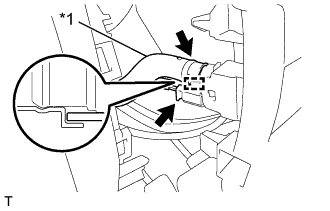
Engage the guide and connect the aspirator hose.
| *1 | Aspirator Hose |
Engage the 4 claws.
Engage the 4 clips to install the No. 1 instrument panel under cover sub-assembly.
Install the 2 screws.
| 12. REMOVE AND INSTALL INSTRUMENT SIDE PANEL (w/o Knee Airbag) |
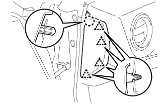 |
Engage the 4 clips and claw to install the instrument side panel.
| 13. INSPECT AND ADJUST SPIRAL CABLE WITH SENSOR SUB-ASSEMBLY |
Check that the ignition switch is off.
Check that the cable is disconnected from the negative (-) battery terminal.
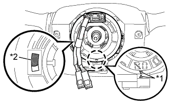 |
Check if the spiral cable sub-assembly is centered.
| *1 | Matching Mark |
| *2 | Colored Part |
If the spiral cable sub-assembly is not centered, center it.
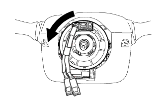 |
Rotate the spiral cable sub-assembly counterclockwise slowly by hand until it stops.
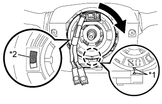 |
Rotate the spiral cable sub-assembly clockwise approximately 2.5 turns to the position where the matching mark is matched.
| *1 | Matching Mark |
| *2 | Colored Part |
| 14. INSTALL STEERING WHEEL ASSEMBLY |