 |
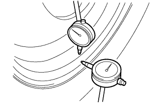
Using a dial indicator, check the runout of the wheel.
| Steel wheel | 2.0 mm (0.0787 in.) (Vertical and lateral) |
| Aluminum wheel | 1.0 mm (0.0394 in.) (Vertical and lateral) |
FRONT WHEEL ALIGNMENT > ADJUSTMENT |
| 1. INSPECT TIRES |
Check the tires for wear and proper inflation pressure.
| Tire Size | Front kPa (kgf/cm2, psi) | Rear kPa (kgf/cm2, psi) |
| 205/55R16 91V | 240 (2.4, 35) | 240 (2.4, 35) |
| 215/45R17 87W | 240 (2.4, 35) | 240 (2.4, 35) |
| T135/80D 16 101M | 420 (4.2, 60) | 420 (4.2, 60) |
|
Using a dial indicator, check the runout of the wheel.
| Steel wheel | 2.0 mm (0.0787 in.) (Vertical and lateral) |
| Aluminum wheel | 1.0 mm (0.0394 in.) (Vertical and lateral) |
| 2. MEASURE VEHICLE HEIGHT |
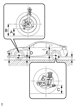 |
Bounce the vehicle up and down at the corners to stabilize the suspension before inspecting the vehicle height.
| Tire Size | Front B - A | Rear C | Front D | Rear E |
| 205/55 R16 | 146 mm (5.75 in.) | 225 mm (8.86 in.) | 375 mm (14.76 in.) | 372 mm (14.65 in.) |
| 215/45 R17 | 146 mm (5.75 in.) | 225 mm (8.86 in.) | 375 mm (14.76 in.) | 372 mm (14.65 in.) |
| 3. INSPECT CAMBER, CASTER AND STEERING AXIS INCLINATION |
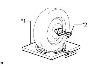 |
Put the front wheel on the center of the alignment tester.
| *1 | Alignment tester |
| *2 | Camber-Caster-Steering Axis Inclination Gauge |
Remove the wheel cap.
Set the camber-caster-steering axis inclination gauge at the center of the axle hub or drive shaft.
Inspect the camber, caster and steering axis inclination.
| Camber | Caster (Reference) | Steering Axis Inclination (Reference) |
| 0 +/- 45' (0 +/- 0.75°) | 5°54' (5.90°) | 15°31' (15.52°) |
Remove the camber-caster-steering axis inclination gauge and attachment.
Install the wheel cap.
If the caster and steering axis inclination are not within the specified values after the camber has been correctly adjusted, recheck the suspension parts for damage and wear.
| 4. ADJUST CAMBER |
Remove the front wheel.
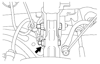 |
Loosen the lower mounting bolt and nut of the front shock absorber assembly and steering knuckle.
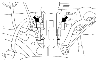 |
Replace the upper mounting bolt of the front shock absorber assembly and steering knuckle with a service bolt. (Part No.: SU003-02818)
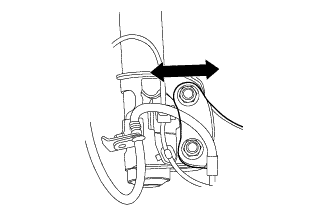 |
Pivot the lower mounting bolt to move the front shock absorber assembly and steering knuckle, and use the play between the bolt and bolt holds of the steering knuckle and front shock absorber assembly to adjust the camber.
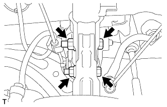 |
Tighten the 2 bolts and 2 new nuts.
Install the front wheel.
Lower the vehicle and bounce it up and down several times to stabilize the front suspension.
Check the camber.
Check the toe-in.
| 5. INSPECT TOE-IN |
Bounce the vehicle up and down at the corners to stabilize the suspension.
Release the parking brake and move the shift lever to the neutral position (for manual transmission).
Release the parking brake and move the shift lever to N (for Automatic transmission).
Push the vehicle straight ahead approximately 5 m (16.4 ft.). (Step A)
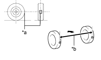 |
Put tread center marks on the rearmost points of the front wheels and measure the distance between the marks (dimension B).
| *a | Tread Center Mark |
| *b | Dimension B |
 | Front of the Vehicle |
Slowly push the vehicle straight ahead to cause the front wheels to rotate 180°. Use the front tire valve as a reference point.
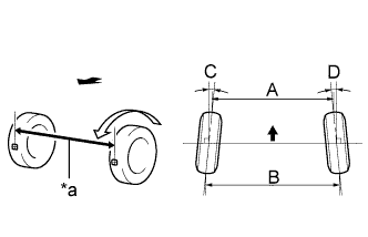 |
Measure the distance between the tread center marks on the front side of the wheels (dimension A).
| *a | Dimension A |
| Front of the Vehicle |
| Specified Condition |
| C + D: 0°00' +/- 0°11' (0.00° +/- 0.19°) |
| B - A: 0 +/- 3.0 mm (0 +/- 0.1181 in.) |
| 6. ADJUST TOE-IN |
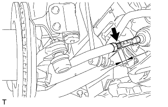 |
Measure the thread lengths of the right and left rack ends.
Remove the rack boot set clips.
Loosen the tie rod end lock nuts.
Adjust the rack ends if the difference in thread length between the right and left rack ends is not within the specified range.
If the toe-in measurement is greater than the specified range (too much toe-out), extend the shorter rack end so that the length difference is within the specified range.
If the toe-in measurement is less than the specified range (too much toe-in), shorten the longer rack end so that the length difference is within the specified range.
Measure the toe-in.
Turn the right and left rack ends by an equal amount to adjust the toe-in.
Make sure that the thread lengths of the right and left rack ends are the same.
Tighten the tie rod end lock nuts.
Place the steering rack boots on the seats and install the steering rack boot clips.
| 7. INSPECT WHEEL ANGLE |
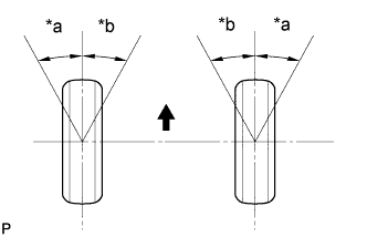 |
Put tread center marks on the rearmost points of a turning radius gauge.
| *a | Inside |
| *b | Outside |
| Front of the Vehicle |
Turn the steering wheel fully to the left and right and measure the turning angle.
| Inside Wheel (Reference) | Outside Wheel (Reference) |
| 36°54' (43.90°) | 31°12' (31.20°) |
| 8. PLACE FRONT WHEELS FACING STRAIGHT AHEAD |
| 9. VSC SENSOR NEUTRAL MEMORIZATION |
| 10. HEIGHT CONTROL SENSOR SIGNAL INITIALIZE (w/ HID Headlight System) |
| 11. ADJUST HEADLIGHT AIMING (w/ HID Headlight System) |