SHIFT LEVER ASSEMBLY > INSTALLATION |
| 1. INSTALL CONTROL SHAFT |
|
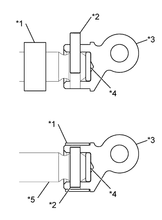
Install a new control shaft collar onto the shift shaft.
Install the shift lever damper and control shaft to the shift shaft.
Using a pin punch (5 mm (0.197 in.)) and a hammer, align the control shaft hole and the shift shaft hole with the cutout of the control shaft collar, and insert the shaft pin from above.
Slide the control shaft collar until it comes into contact with the stopper of the control shaft, then stake it to the cutout.
| *1 | Control Shaft Collar |
| *2 | Shaft Pin |
| *3 | Control Shaft |
| *4 | Shift Lever Damper |
| *5 | Shift Shaft |
| 2. INSTALL FLOOR SHIFT CONTROL SHAFT |
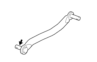 |
Apply a light coat of MP grease to the floor shift control shaft.
 | MP grease |
Install the floor shift control shaft and 2 collars to the control shaft.
Install the plate washer and clip.
| 3. INSTALL SHIFT LEVER RETAINER BUSHING |
Install the 4 shift lever retainer bushings to the floor shift control shift lever retainer.
| 4. INSTALL FLOOR SHIFT CONTROL SHIFT LEVER RETAINER |
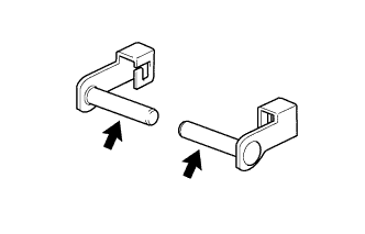 |
Apply a light coat of MP grease to new 2 shift lever pins.
| MP grease |
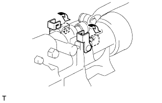 |
Install the floor shift control shift lever retainer with the 2 shift lever pins.
Secure the shift lever pins to the extension housing sub-assembly.
| 5. INSTALL MANUAL TRANSMISSION ASSEMBLY |
| 6. INSTALL SHIFT AND SELECT LEVER BOOT |
Temporarily install a new shift and select lever boot to the floor shift lever assembly.
| 7. INSTALL FLOOR SHIFT LEVER ASSEMBLY |
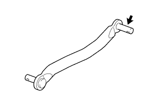 |
Apply a light coat of MP grease to the floor shift control shaft.
| MP grease |
Install the O-ring and 2 bushings to the floor shift lever assembly.
Install the plate washer to the floor shift lever assembly.
Install the shift lever assembly with the clip.
Install the shift and select lever boot.
| 8. INSTALL FLOOR SHIFT CONTROL SHIFT LEVER RETAINER SUB-ASSEMBLY |
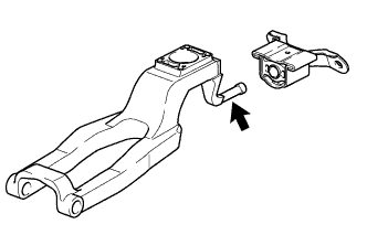 |
Apply a light coat of MP grease to the floor shift control shift lever retainer sub-assembly.
| MP grease |
Install the floor shift control shift lever retainer sub-assembly to the floor shift control shift lever retainer.
Install the floor shift control shift lever retainer sub-assembly with the 2 bolts.
| 9. INSTALL PROPELLER SHAFT WITH CENTER BEARING ASSEMBLY |
| 10. INSTALL SHIFT LEVER CAP |
Install the shift lever cap with the 4 bolts.
| 11. ADJUST SHIFT LEVER POSITION |
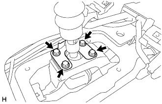 |
Loosen the 4 bolts of the shift lever cap. [*1]
Move the shift lever to 2nd. [*2]
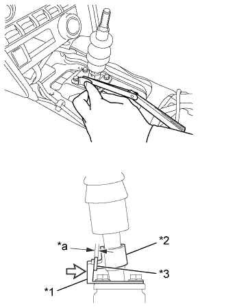 |
Insert a 1 mm (0.03937 in.) feeler gauge between the stopper and the shift lever cap, and push the shift lever cap against the stopper. [*3]
| *1 | Shift Lever Cap |
| *2 | Stopper |
| *3 | Feeler Gauge |
| *a | 1.0 mm (0.03937 in.) |
 | Push |
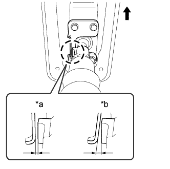 |
While keeping the clearance gap between the stopper and the shift lever cap parallel, tighten the 4 bolts to the specified torque. [*4]
| *a | Correct |
| *b | Incorrect |
| Front of vehicle |
Depress the clutch pedal and check that the shift lever can be moved to 1st and 2nd.
If the shift lever cannot be moved to 1st and 2nd, repeat steps [*1] to [*4] , decreasing the thickness of the feeler gauge in increments of 0.2 mm (0.00787 in.) until the shift lever can be moved to 1st and 2nd.
Depress the clutch pedal and check that the shift lever can be moved to 1st and 2nd.
After adjusting the position of the shift lever, apply MP grease to the stopper and shift lever cap.
| 12. INSTALL SHIFT LEVER BOOT |
Install the shift lever boot and shift and select lever retainer with the 4 bolts.
Connect the wire harness clamp.
Install the shift and select lever cover with the 2 clips.
| 13. INSTALL CONSOLE BOX ASSEMBLY |
| 14. CONNECT CABLE TO NEGATIVE BATTERY TERMINAL |