 |
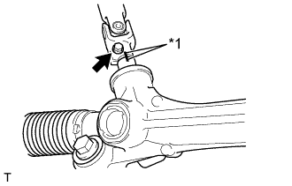
Align the matchmarks and install the steering intermediate shaft to the rack and pinion power steering gear assembly.
| *1 | Matchmark |
STEERING GEAR > INSTALLATION |
| 1. INSTALL RACK AND PINION POWER STEERING GEAR ASSEMBLY |
Install the rack and pinion power steering gear assembly with the 2 bolts.
| 2. CONNECT STEERING INTERMEDIATE SHAFT ASSEMBLY |
|
Align the matchmarks and install the steering intermediate shaft to the rack and pinion power steering gear assembly.
| *1 | Matchmark |
Install the new bolt.
| 3. CONNECT TIE ROD END SUB-ASSEMBLY LH |
Connect the tie rod end sub-assembly LH to the steering knuckle with the nut.
Install a new cotter pin.
| 4. CONNECT TIE ROD END SUB-ASSEMBLY RH |
| 5. INSTALL FRONT STABILIZER BAR |
Install the front stabilizer bar together with the rear body mounting cushion sub-assembly LH and RH to the front suspension cross member with the new 8 bolts.
| 6. CONNECT FRONT STABILIZER LINK ASSEMBLY LH |
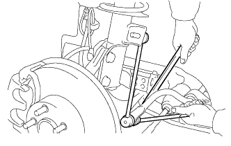 |
Connect the front stabilizer link assembly LH to the front stabilizer bar with the nut.
| 7. CONNECT FRONT STABILIZER LINK ASSEMBLY RH |
| 8. INSTALL NO. 2 ENGINE UNDER COVER |
Install the 7 bolts and the No. 2 engine under cover.
| 9. INSTALL NO. 1 ENGINE UNDER COVER |
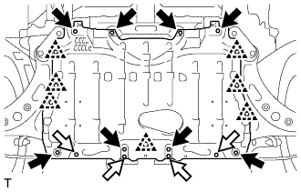 |
Install the No. 1 engine under cover with the 12 bolts and engage the 7 clips.
 | Bolt A |
 | Bolt B |
| 10. INSTALL FRONT WHEELS |
| 11. INSPECT AND ADJUST FRONT WHEEL ALIGNMENT |
| 12. INSPECT STEERING WHEEL CENTER POINT |
| 13. VSC SENSOR NEUTRAL MEMORIZATION |