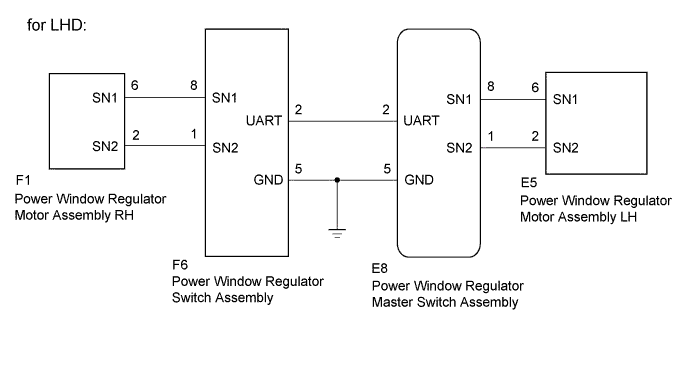
DTC B2313 Driver Side Glass Position Initialization Incomplete |
DTC B2316 Passenger Side Glass Position Initialization Incomplete |
| DTC No. | DTC Detection Condition | Trouble Area |
| B2313 |
|
|
| B2316 |
|
|
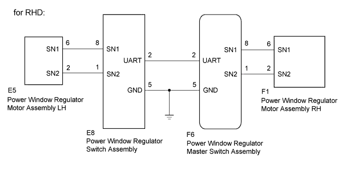
| 1.PERFORM INITIALIZATION |
Turn the ignition switch to ON.
Initialize the power window regulator master switch assembly or power window regulator switch assembly (Click here).
| NEXT | |
 |
| 2.CHECK DTC OUTPUT |
Clear the DTC (Click here).
Check for DTCs (Click here).
| Result | Proceed to |
| No DTCs output | A |
| DTCs B2311 or B2314 is output | B |
| DTCs B2312 or B2315 is output | B |
| DTC B2313 is output | C |
| DTC B2316 is output | D |
|
| ||||
|
| ||||
|
| ||||
| A | ||
 | ||
| ||
| 3.CHECK POWER WINDOW REGULATOR MASTER SWITCH ASSEMBLY |
Using an oscilloscope, check the waveform.
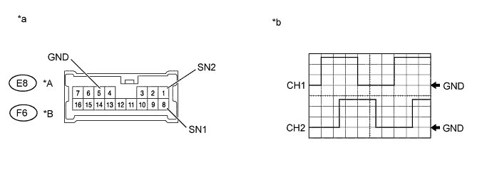
| *A | for LHD | *B | for RHD |
| *a | Component with harness connected (Power Window Regulator Master Switch Assembly) | *b | Waveform |
| Tester Connection | Condition | Tool Setting | Specified Condition |
| CH1: E8-8 (SN1) - E8-5 (GND)*1 CH2: E8-1 (SN2) - E8-5 (GND)*1 CH1: F6-8 (SN1) - F6-5 (GND)*2 CH2: F6-1 (SN2) - F6-5 (GND)*2 | Ignition switch ON, power window regulator master switch assembly OFF → UP or DOWN | 5 V/DIV., 2 ms./DIV. | Pulse generation (See waveform) |
| Result | Proceed to |
| NG | A |
| OK | B |
|
| ||||
| A | |
|
| 4.CHECK HARNESS AND CONNECTOR (POWER WINDOW REGULATOR MASTER SWITCH ASSEMBLY - POWER WINDOW REGULATOR MOTOR ASSEMBLY (FOR DRIVER SIDE)) |
Disconnect the E8*1 or F6*2 power window regulator master switch assembly connector.
Disconnect the E5*1 or F1*2 power window regulator motor assembly (for driver side) connector.
Measure the resistance according to the value(s) in the table below.
| Tester Connection | Condition | Specified Condition |
| E8-8 (SN1) - E5-6 (SN1)*1 | Always | Below 1 Ω |
| E8-1 (SN2) - E5-2 (SN2)*1 | Always | Below 1 Ω |
| F6-8 (SN1) - F1-6 (SN1)*2 | Always | Below 1 Ω |
| F6-1 (SN2) - F1-2 (SN2)*2 | Always | Below 1 Ω |
| Tester Connection | Condition | Specified Condition |
| E8-8 (SN1) or E5-6 (SN1) - Body ground*1 | Always | 10 kΩ or higher |
| E8-1 (SN2) or E5-2 (SN2) - Body ground*1 | Always | 10 kΩ or higher |
| F6-8 (SN1) or F1-6 (SN1) - Body ground*2 | Always | 10 kΩ or higher |
| F6-1 (SN2) or F1-2 (SN2) - Body ground*2 | Always | 10 kΩ or higher |
|
| ||||
| OK | ||
| ||
| ||
| 5.CHECK POWER WINDOW REGULATOR SWITCH ASSEMBLY |
Using an oscilloscope, check the waveform.
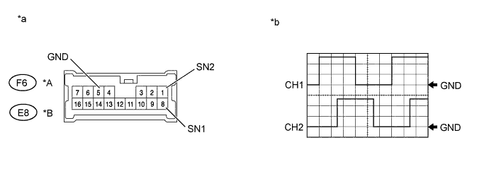
| *A | for LHD | *B | for RHD |
| *a | Component with harness connected (Power Window Regulator Switch Assembly) | *b | Waveform |
| Tester Connection | Condition | Tool Setting | Specified Condition |
| CH1: F6-8 (SN1) - F6-5 (GND)*1 CH2: F6-1 (SN2) - F6-5 (GND)*1 CH1: E8-8 (SN1) - E8-5 (GND)*2 CH2: E8-1 (SN2) - E8-5 (GND)*2 | Ignition switch ON, power window regulator switch assembly OFF → UP or DOWN | 5 V/DIV., 2 ms./DIV. | Pulse generation (See waveform) |
| Result | Proceed to |
| NG | A |
| OK | B |
|
| ||||
| A | |
|
| 6.CHECK HARNESS AND CONNECTOR (POWER WINDOW REGULATOR SWITCH - POWER WINDOW REGULATOR MOTOR (FOR FRONT PASSENGER SIDE)) |
Disconnect the F6*1 or E8*2 power window regulator switch assembly connector.
Disconnect the F1*1 or E5*2 power window regulator motor assembly (for passenger side) connector.
Measure the resistance according to the value(s) in the table below.
| Tester Connection | Condition | Specified Condition |
| F6-8 (SN1) - F1-6 (SN1)*1 | Always | Below 1 Ω |
| F6-1 (SN2) - F1-2 (SN2)*1 | Always | Below 1 Ω |
| E8-8 (SN1) - E5-6 (SN1)*2 | Always | Below 1 Ω |
| E8-1 (SN2) - E5-2 (SN2)*2 | Always | Below 1 Ω |
| Tester Connection | Condition | Specified Condition |
| F6-8 (SN1) or F1-6 (SN1) - Body ground*1 | Always | 10 kΩ or higher |
| F6-1 (SN2) or F1-2 (SN2) - Body ground*1 | Always | 10 kΩ or higher |
| E8-8 (SN1) or E5-6 (SN1) - Body ground*2 | Always | 10 kΩ or higher |
| E8-1 (SN2) or E5-2 (SN2) - Body ground*2 | Always | 10 kΩ or higher |
|
| ||||
| OK | ||
| ||
| ||

