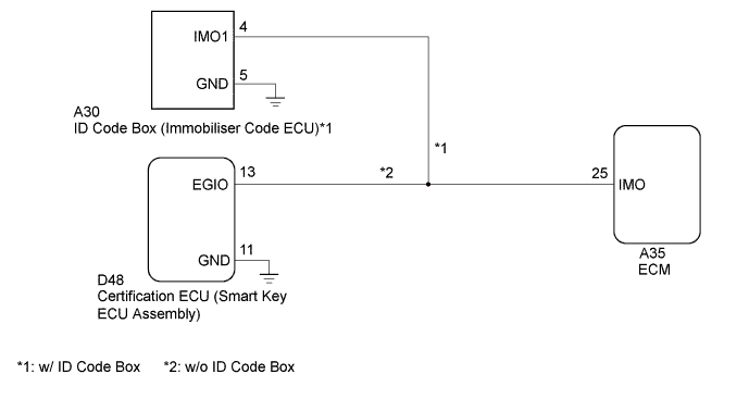
DTC B1572 Immobiliser System Communication Malfunction |
| DTC Code | DTC Detection Condition | Trouble Area | DTC Output Confirmation Operation |
| B1572 | When there is a problem in communication between the ID code box (immobiliser code ECU)*1 or certification ECU (smart key ECU assembly)*2 and the ECM (1 trip detection logic*3): |
| Engine switch on (IG) |
| Vehicle Condition when Malfunction Detected | Fail-safe Operation when Malfunction Detected |
| Engine cannot be started | - |
| DTC Code | Data List and Active Test |
| B1572 | Entry&Start
|
| 1.READ VALUE USING GTS (IMMOBILISER) |
Connect the GTS to the DLC3.
Turn the engine switch on (IG).
Turn the GTS on.
Enter the following menus: Body Electrical / Entry & Start / Data List.
According to the display on the GTS, read the Data List.
| Tester Display | Measurement Item/Range | Normal Condition | Diagnostic Note |
| Immobiliser | Engine immobiliser system status when power source mode on (IG) / Unset or Set | Set: Engine immobiliser set (engine start prohibited) (engine switch off) Unset: Engine immobiliser unset (engine start permitted) [engine switch on (ACC) or on (IG)] | If "Set" is displayed, the engine start function is prohibited. |
|
| ||||
| OK | |
 |
| 2.CHECK VEHICLE CONDITION |
Check the vehicle condition.
| Result | Proceed to |
| w/ ID Code Box | A |
| w/o ID Code Box | B |
|
| ||||
| A | |
|
| 3.CHECK HARNESS AND CONNECTOR |
Disconnect the A30 ID code box (immobiliser code ECU) connector.
Disconnect the A35 ECM connector.
Measure the resistance according to the value(s) in the table below.
| Tester Connection | Condition | Specified Condition |
| A30-4 (IMO1) - A35-25 (IMO) | Always | Below 1 Ω |
| A30-4 (IMO1) - Body ground | Always | 10 kΩ or higher |
|
| ||||
| OK | |
|
| 4.REPLACE ECM |
Temporarily replace the ECM with a new one (Click here).
| NEXT | |
|
| 5.REGISTER ECU COMMUNICATION ID |
Register the ECU communication ID (Refer to Service Bulletin).
Check that the engine can be started.
|
| ||||
| OK | ||
 | ||
| ||
| 6.CHECK HARNESS AND CONNECTOR |
Disconnect the D48 certification ECU (smart key ECU assembly) connector.
Disconnect the A35 ECM connector.
Measure the resistance according to the value(s) in the table below.
| Tester Connection | Condition | Specified Condition |
| D48-13 (EGIO) - A35-25 (IMO1) | Always | Below 1 Ω |
| D48-13 (EGIO) - Body ground | Always | 10 kΩ or higher |
|
| ||||
| OK | |
|
| 7.REPLACE ECM |
Temporarily replace the ECM with a new one (Click here).
| NEXT | |
|
| 8.REGISTER ECU COMMUNICATION ID |
Register the ECU communication ID (Refer to Service Bulletin).
Check that the engine can be started.
|
| ||||
| OK | ||
| ||
| ||

