
ENTRY AND START SYSTEM (for Start Function) > Engine does not Start |
| Problem Symptom | Data List Item | Active Test Item |
| Engine does not start | Power Source Control
Entry & Start
Engine
| - |
| 1.CHECK BATTERY |
Measure the battery voltage.
| NEXT | |
|
| 2.CHECK DTC (ALL) |
Using the GTS, confirm the output of DTCs for all systems.
|
| ||||
| OK | |
|
| 3.CHECK WAVE ENVIRONMENT |
If the problem occurs in certain locations or times of day, the possibility of wave interference is high.
| NEXT | |
|
| 4.CHECK ENGINE SWITCH CONDITION |
Get into the vehicle while carrying an electrical key transmitter assembly.
Move the shift lever to P*.
With the brake pedal*1 or clutch pedal*2 released, check that pressing the engine switch causes the power source mode to change.
| Result | Proceed to |
| Power source mode changes as follows (normal): off → on (ACC) → on (IG) → off | A |
| Power source mode does not change to on (IG) or on (ACC) | B |
| Power source mode does not change to on (IG) but does change to on (ACC) | C |
| Power source mode does not change to on (ACC) but does change to on (IG) | D |
|
| ||||
|
| ||||
|
| ||||
| A | |
|
| 5.CHECK CRANKING FUNCTION |
Get into the vehicle while carrying the electrical key transmitter assembly.
Move the shift lever to P*.
Depress the brake pedal*1 or clutch pedal*2.
Confirm that the entry key indicator in the combination meter assembly illuminates in green, and then press the engine switch and check that the engine cranks.
| Result | Proceed to |
| NG | A |
| OK | B |
|
| ||||
| A | |
|
| 6.READ VALUE USING GTS (IMMOBILISER) |
Connect the GTS to the DLC3.
Turn the engine switch on (IG).
Turn the GTS on.
Enter the following menus: Body Electrical / Entry & Start / Data List.
According to the display on the GTS, read the Data List.
| Tester Display | Measurement Item/Range | Normal Condition | Diagnostic Note |
| Immobiliser | State of immobiliser system determined by certification ECU (smart key ECU assembly) / Set or Unset | Set: Engine immobiliser set (engine start prohibited) (engine switch off) Unset: Engine immobiliser unset (engine start permitted) (engine switch on (ACC) or on (IG)) |
|
| Result | Proceed to |
| OK | A |
| NG (w/ ID Code Box) | B |
| NG (w/o ID Code Box) | C |
|
| ||||
|
| ||||
| A | |
|
| 7.CHECK COMBINATION METER ASSEMBLY (ENTRY KEY INDICATOR LIGHT) |
Get into the vehicle while carrying the electrical key transmitter assembly, move the shift lever to P*1, depressing the brake pedal*1 or clutch pedal*2 and check that the entry key indicator light in the combination meter assembly changes.
| Result | Proceed to |
| OK | A |
| NG (for Automatic Transmission) | B |
| NG (for Manual Transaxle) | C |
|
| ||||
|
| ||||
| A | |
|
| 8.READ VALUE USING GTS (STARTER REQUEST SIGNAL) |
Connect the GTS to the DLC3.
Turn the engine switch on (IG).
Turn the GTS on.
Enter the following menus: Body Electrical / Power Source Control / Data List.
According to the display on the GTS, read the Data List.
| Tester Display | Measurement Item/Range | Normal Condition | Diagnostic Note |
| Starter Request Signal | Condition of engine start command signal / OFF or ON | OFF: Engine switch released after approximately 1 second elapses ON: Engine switch pressed and held while carrying electrical key transmitter assembly with shift lever in P*1 and brake pedal*1 or clutch pedal*2 depressed |
|
|
| ||||
| OK | |
|
| 9.CHECK HARNESS AND CONNECTOR (CERTIFICATION ECU (SMART KEY ECU ASSEMBLY) - BODY GROUND) |
Disconnect the D48 certification ECU (smart key ECU assembly) connector.
Disconnect the A33 ECM connector.
Measure the resistance according to the value(s) in the table below.
| Tester Connection | Condition | Specified Condition |
| D48-7 (STSW) - A33-17 (STSW) | Always | Below 1 Ω |
| D48-7 (STSW) - Body ground | Always | 10 kΩ or higher |
|
| ||||
| OK | ||
 | ||
| ||
| 10.READ VALUE USING GTS (S CODE CHECK) |
Connect the GTS to the DLC3.
Turn the engine switch on (IG).
Turn the GTS on.
Enter the following menus: Body Electrical / Entry & Start / Data List.
According to the display on the GTS, read the Data List.
| Tester Display | Measurement Item/Range | Normal Condition | Diagnostic Note |
| S Code Check | Verification result between certification ECU (smart key ECU assembly) and ID code box (immobiliser code ECU) / OK or NG | OK: Verification result normal NG: Verification result abnormal | When NG is displayed:
|
|
| ||||
| OK | |
|
| 11.CHECK STEERING LOCK |
Check that the steering unlocks when the engine switch is turned on (ACC).
|
| ||||
| OK | |
|
| 12.READ VALUE USING GTS (IMMOBILISER) |
Connect the GTS to the DLC3.
Turn the engine switch on (IG).
Turn the GTS on.
Enter the following menus: Body Electrical / Entry & Start / Data List.
According to the display on the GTS, read the Data List.
| Tester Display | Measurement Item/Range | Normal Condition | Diagnostic Note |
| Immobiliser | State of immobiliser system determined by certification ECU (smart key ECU assembly) / Set or Unset | Unset: Engine immobiliser unset (engine switch on [ACC] or on [IG]) Set: Engine immobiliser set (engine switch off) |
|
| Result | Proceed to |
| OK | A |
| NG (w/ ID Code Box) | B |
| NG (w/o ID Code Box) | C |
|
| ||||
|
| ||||
| A | |
|
| 13.READ VALUE USING GTS (STARTER REQUEST SIGNAL) |
Connect the GTS to the DLC3.
Turn the engine switch on (IG).
Turn the GTS on.
Enter the following menus: Body Electrical / Power Source Control / Data List.
According to the display on the GTS, read the Data List.
| Tester Display | Measurement Item/Range | Normal Condition | Diagnostic Note |
| Starter Request Signal | Condition of engine start command signal / OFF or ON | OFF: Engine switch released after approximately 1 second elapses ON: Engine switch pressed and held while carrying electrical key transmitter assembly with shift lever in P*1 and brake pedal*1 or clutch pedal*2 depressed |
|
|
| ||||
| OK | ||
| ||
| ||
| 14.READ VALUE USING GTS (NEUTRAL SW/ CLUTCH SW, SHIFT SW STATUS P OR N) |
Connect the GTS to the DLC3.
Turn the engine switch on (IG).
Turn the GTS on.
Enter the following menus: Body Electrical / Power Source Control / Data List.
According to the display on the GTS, read the Data List.
| Tester Display | Measurement Item/Range | Normal Condition | Diagnostic Note |
| Neutral SW / Clutch SW | Shift position (P, N) / OFF or ON | OFF: Shift lever not in P or N or released ON: Shift lever in P or N depressed |
|
| Tester Display | Measurement Item/Range | Normal Condition | Diagnostic Note |
| Shift SW Status (P Range) | Condition of park/neutral position switch / OFF or ON | OFF: Shift lever not in P ON: Shift lever in P | When malfunctioning, the engine will not crank. |
| Shift SW Status (N Range) | Condition of park/neutral position switch / OFF or ON | OFF: Shift lever not in N ON: Shift lever in N | When malfunctioning, the engine will not crank. |
|
| ||||
| OK | |
|
| 15.READ VALUE USING GTS (STOP LIGHT SWITCH1) |
Connect the GTS to the DLC3.
Turn the engine switch on (IG).
Turn the GTS on.
Enter the following menus: Body Electrical / Power Source Control / Data List.
According to the display on the GTS, read the Data List.
| Tester Display | Measurement Item/Range | Normal Condition | Diagnostic Note |
| Stop Light Switch1 | State of brake pedal / OFF or ON | OFF: Brake pedal released ON: Brake pedal depressed |
|
|
| ||||
| OK | ||
| ||
| ||
| 16.INSPECT PARK/NEUTRAL POSITION SWITCH ASSEMBLY |
Remove the park/neutral position switch assembly (Click here).
Inspect the park/neutral position switch assembly (Click here).
|
| ||||
| OK | |
|
| 17.CHECK HARNESS AND CONNECTOR (CERTIFICATION ECU (SMART KEY ECU ASSEMBLY) - PARK/NEUTRAL POSITION SWITCH ASSEMBLY) |
Disconnect the D48 certification ECU (smart key ECU assembly) connector.
Disconnect the L2 park/neutral position switch assembly connector.
Measure the resistance according to the value(s) in the table below.
| Tester Connection | Condition | Specified Condition |
| D48-5 (N-SW) - L2-4 | Always | Below 1 Ω |
| L2-5 - Body ground | Always | Below 1 Ω |
| D48-5 (N-SW) - Body ground | Always | 10 kΩ or higher |
|
| ||||
| OK | ||
| ||
| ||
| 18.INSPECT STOP LIGHT SWITCH ASSEMBLY |
Remove the stop light switch assembly (Click here).
Inspect the stop light switch assembly (Click here).
|
| ||||
| OK | |
|
| 19.CHECK HARNESS AND CONNECTOR (NOISE FILTER - CERTIFICATION ECU (SMART KEY ECU ASSEMBLY)) |
Disconnect the D48 certification ECU (smart key ECU assembly) connector.
Disconnect the A13 noise filter connector.
Measure the resistance according to the value(s) in the table below.
| Tester Connection | Condition | Specified Condition |
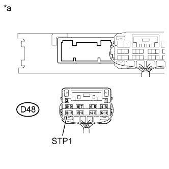
| D48-18 (STP1) - A13-4 | Always | Below 1 Ω |
| D48-18 (STP1) - Body ground | Always | 10 kΩ or higher |
 |
Reconnect the A13 noise filter connector.
Measure the voltage according to the value(s) in the table below.
| Tester Connection | Condition | Specified Condition |
| D48-18 (STP1) - Body ground | Brake pedal released | Below 1 V |
| Brake pedal depressed | 9 V or higher |
| *a | Rear view of wire harness connector (Certification ECU (Smart Key ECU Assembly)) |
|
| ||||
| OK | ||
| ||
| ||
| 20.READ VALUE USING GTS (NEUTRAL SW/ CLUTCH SW) |
Connect the GTS to the DLC3.
Turn the engine switch on (IG).
Turn the GTS on.
Enter the following menus: Body Electrical / Power Source Control / Data List.
According to the display on the GTS, read the Data List.
| Tester Display | Measurement Item/Range | Normal Condition | Diagnostic Note |
| Neutral SW / Clutch SW | State of clutch pedal / OFF or ON | OFF: Clutch pedal released ON: Clutch pedal depressed |
|
|
| ||||
| OK | ||
| ||
| ||
| 21.INSPECT CLUTCH START SWITCH ASSEMBLY |
Remove the clutch start switch assembly.
Inspect the clutch start switch assembly.
| Result | Proceed to |
| OK | A |
| NG (for LHD) | B |
| NG (for RHD) | C |
|
| ||||
|
| ||||
| A | |
|
| 22.CHECK HARNESS AND CONNECTOR (CERTIFICATION ECU (SMART KEY ECU ASSEMBLY) - CLUTCH START SWITCH ASSEMBLY) |
Disconnect the D48 certification ECU (smart key ECU assembly) connector.
Disconnect the A20 clutch start switch assembly connector.
Measure the resistance according to the value(s) in the table below.
| Tester Connection | Condition | Specified Condition |
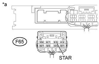
| D48-10 (CLUT) - A20-2 | Always | Below 1 Ω |
| D48-10 (CLUT) - Body ground | Always | 10 kΩ or higher |
Reconnect the A20 clutch start switch assembly connector.
 |
Measure the voltage according to the value(s) in the table below.
| Tester Connection | Switch Condition | Specified Condition |
| D48-10 (CLUT) - Body ground | Clutch pedal released → Clutch pedal depressed | 1 V or less → 9 V or higher |
|
| ||||
| OK | ||
| ||
| ||
| 23.REPLACE CERTIFICATION ECU (SMART KEY ECU ASSEMBLY) |
Replace the certification ECU (smart key ECU assembly) with a new one.
Perform the registration procedures (Refer to Service Bulletin).
Use the Data List to check if S code certification is functioning properly again.
| Tester Display | Measurement Item/Range | Normal Condition | Diagnostic Note |
| S Code Check | Verification result between certification ECU (smart key ECU assembly) and ID code box (immobiliser code ECU) / OK or NG | OK: Verification result normal NG: Verification result abnormal | When NG is displayed:
|
|
| ||||
| OK | ||
| ||
| ||
| 24.REPLACE ID CODE BOX (IMMOBILISER CODE ECU) |
Replace the ID code box (immobiliser code ECU) with a new one.
Perform the registration procedures (Refer to Service Bulletin).
Use the Data List to check if S code certification is functioning properly again.
| Tester Display | Measurement Item/Range | Normal Condition | Diagnostic Note |
| S Code Check | Verification result between certification ECU (smart key ECU assembly) and ID code box (immobiliser code ECU) / OK or NG | OK: Verification result normal NG: Verification result abnormal | When NG is displayed:
|
| NEXT | ||
| ||
| ||
| 25.READ VALUE USING GTS (STEERING UNLOCK SWITCH) |
Connect the GTS to the DLC3.
Turn the engine switch on (IG).
Turn the GTS on.
Enter the following menus: Body Electrical / Power Source Control / Data List.
According to the display on the GTS, read the Data List.
| Tester Display | Measurement Item/Range | Normal Condition | Diagnostic Note |
| Steering Unlock Switch | State of steering unlock sensor signal output from steering lock actuator assembly / OFF or ON | OFF: Steering locked ON: Steering unlocked |
|
|
| ||||
| OK | ||
| ||
| ||
| 26.READ VALUE USING GTS (L CODE CHECK) |
Connect the GTS to the DLC3.
Turn the engine switch on (IG).
Turn the GTS on.
Enter the following menus: Body Electrical / Entry & Start / Data List.
According to the display on the GTS, read the Data List.
| Tester Display | Measurement Item/Range | Normal Condition | Diagnostic Note |
| L Code Check | Verification result between ID code box (immobiliser code ECU) and steering lock actuator assembly (steering lock ECU) / OK or NG | OK: Verification result normal NG: Verification result abnormal | When NG is displayed:
|
|
| ||||
| OK | |
|
| 27.REPLACE STEERING LOCK ACTUATOR ASSEMBLY (STEERING LOCK ECU) |
Replace the steering lock actuator assembly (steering lock ECU) with a new one (Click here).
Perform the registration procedures (Refer to Service Bulletin).
Turn the engine switch on (IG).
Operate the steering wheel and check the steering condition.
| NEXT | ||
| ||
| ||
| 28.REPLACE STEERING LOCK ACTUATOR ASSEMBLY (STEERING LOCK ECU) |
Replace the steering lock actuator assembly (steering lock ECU) with a new one (Click here).
Perform the registration procedures (Refer to Service Bulletin).
Use the Data List to check if L code certification is functioning properly again.
| Tester Display | Measurement Item/Range | Normal Condition | Diagnostic Note |
| L Code Check | Verification result between ID code box (immobiliser code ECU) and steering lock actuator assembly (steering lock ECU) / OK or NG | OK: Verification result normal NG: Verification result abnormal | When NG is displayed:
|
| Result | Proceed to |
| OK | A |
| NG (w/ ID Code Box) | B |
| NG (w/o ID Code Box) | C |
|
| ||||
|
| ||||
| A | ||
| ||
| ||
| 29.REPLACE CERTIFICATION ECU (SMART KEY ECU ASSEMBLY) |
Replace the certification ECU (smart key ECU assembly) with a new one.
Perform the registration procedures (Refer to Service Bulletin for registration).
Use the Data List to check if S code certification is functioning properly again.
| Tester Display | Measurement Item/Range | Normal Condition | Diagnostic Note |
| S Code Check | Verification result between certification ECU (smart key ECU assembly) and ID code box (immobiliser code ECU) / OK or NG | OK: Verification result normal NG: Verification result abnormal | When NG is displayed:
|
|
| ||||
| OK | ||
| ||
| ||
| 30.REPLACE ID CODE BOX (IMMOBILISER CODE ECU) |
Replace the ID code box (immobiliser code ECU) with a new one.
Perform the registration procedures (Refer to Service Bulletin).
Use the Data List to check if S code certification is functioning properly again.
| Tester Display | Measurement Item/Range | Normal Condition | Diagnostic Note |
| S Code Check | Verification result between certification ECU (smart key ECU assembly) and ID code box (immobiliser code ECU) / OK or NG | OK: Verification result normal NG: Verification result abnormal | When NG is displayed:
|
| NEXT | ||
| ||
| ||

