FA20 ENGINE MECHANICAL CYLINDER HEAD GASKET INSTALLATION
PROCEDURE

 11116
1.INSTALL NO. 2 CYLINDER HEAD GASKET
Operate the engine stand so that the bank 2 side faces upward.
Clean the bolt holes in the cylinder block (bank 2).
- NOTICE:
-
To avoid erroneous tightening of the bolts, clean out the bolt holes sufficiently by blowing with compressed air to eliminate engine coolant, etc.
Using a sealer gun, apply seal packing to both sides of the No. 2 cylinder head gasket as shown in the illustration.
- Seal packing:
Three Bond 1217G, 1217H or equivalent
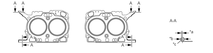
| *a | 0 to 1.0 mm (0 to 0.039in.) | *b | φ2,0 to 4.0 mm (0.079 to 0.158 in.) |
| *c | Edge of the gasket | - | - |
- NOTICE:
- ·
Clean and degrease the contact surface.
·Install the cylinder head sub-assembly LH within 5 minutes of applying the seal packing.
Place the No. 2 cylinder head gasket on the cylinder block (bank 2).
11102
2.INSTALL CYLINDER HEAD SUB-ASSEMBLY LH
Clean the threads of the cylinder head bolts and apply sufficient engine oil to the washers and threads of the bolts.
Mount the cylinder head sub-assembly LH on the cylinder block (bank 2).
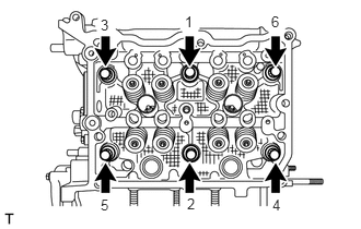
Tighten the 6 cylinder head bolts in the order shown in the illustration.
- Torque:
- 20 N*m (204 kgf*cm, 15 ft.*lbf)
Tighten the 6 cylinder head bolts further in the same order above.
- Torque:
- 100 N*m (1020 kgf*cm, 74 ft.*lbf)
- NOTICE:
-
If the bolt makes a stick-slip sound during tightening, repeat the procedure from the cylinder head gasket installation after cleaning and completely drying the bolt holes and contact surfaces.
- HINT:
-
In that case, the No. 2 cylinder head gasket can be reused.
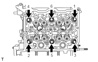
Loosen the 6 cylinder head bolts by 360 ° in the order shown in the illustration.
Tighten the 6 cylinder head bolts in the order shown in the illustration.
- Torque:
- 20 N*m (204 kgf*cm, 15 ft.*lbf)
Tighten the 6 cylinder head bolts further in the same order above.
- Torque:
- 42 N*m (428 kgf*cm, 31 ft.*lbf)
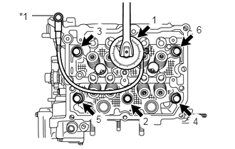
Using an angle gauge, tighten the 6 cylinder head bolts another 100 ° in the order shown in the illustration.
- HINT:
-
Temporarily install the appropriate bolt for angle gauge if necessary.
| *1 | Temporary Bolt |
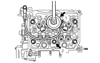
Using an angle gauge, tighten the 2 cylinder head bolts another 100 ° in the order shown in the illustration.
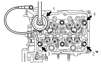
Using an angle gauge, tighten the 4 cylinder head bolts another 50 ° in the order shown in the illustration.
11104A
3.INSTALL CAMSHAFT HOUSING SUB-ASSEMBLY LH
11115
4.INSTALL CYLINDER HEAD GASKET
Operate the engine stand so that the bank 1 side faces upward.
Clean the bolt holes in the cylinder block (bank 1).
- NOTICE:
-
To avoid erroneous tightening of the bolts, clean out the bolt holes sufficiently by blowing with compressed air to eliminate engine coolant, etc.
Using a sealer gun, apply seal packing to both sides of the cylinder head gasket as shown in the illustration.
- Seal packing:
Three Bond 1217G, 1217H or equivalent
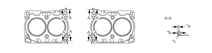
| *a | 0 to 1.0 mm (0 to 0.039in.) | *b | φ2,0 to 4.0 mm (0.079 to 0.158 in.) |
| *c | Edge of the gasket | - | - |
- NOTICE:
- ·
Clean and degrease the contact surface.
·Install the cylinder head sub-assembly RH within 5 minutes of applying the seal packing.
Place the cylinder head gasket on the cylinder block (bank 1).
11101
5.INSTALL CYLINDER HEAD SUB-ASSEMBLY RH
Clean the threads of the cylinder head bolts and apply sufficient engine oil to the washers and threads of the bolts.
Mount the cylinder head sub-assembly RH on the cylinder block (bank 1).
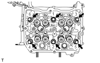
Tighten the 6 cylinder head bolts in the order shown in the illustration.
- Torque:
- 20 N*m (204 kgf*cm, 15 ft.*lbf)
Tighten the 6 cylinder head bolts further in the same order as above.
- Torque:
- 100 N*m (1020 kgf*cm, 74 ft.*lbf)
- NOTICE:
-
If the bolt makes a stick-slip sound during tightening, repeat the procedure from the cylinder head gasket installation after cleaning and completely drying the bolt holes and contact surfaces.
- HINT:
-
In that case, the cylinder head gasket can be reused.
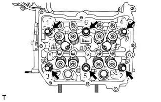
Loosen the 6 cylinder head bolts by 360 ° in the order shown in the illustration.
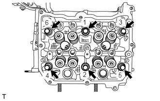
Tighten the 6 cylinder head bolts in the order shown in the illustration.
- Torque:
- 20 N*m (204 kgf*cm, 15 ft.*lbf)
Tighten the 6 cylinder head bolts further in the same order above.
- Torque:
- 42 N*m (428 kgf*cm, 31 ft.*lbf)
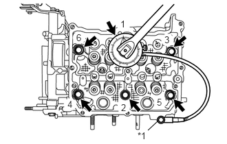
Using an angle gauge, tighten the 6 cylinder head bolts another 100 ° in the order shown in the illustration.
- HINT:
-
Temporarily install the appropriate bolt for angle gauge if necessary.
| *1 | Temporary Bolt |
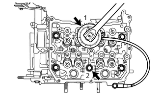
Using an angle gauge, tighten the 2 cylinder head bolts another 100 ° in the order shown in the illustration.
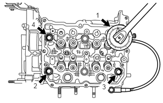
Using an angle gauge, tighten the 4 cylinder head bolts another 50 ° in the order shown in the illustration.
11103C
6.INSTALL CAMSHAFT HOUSING SUB-ASSEMBLY RH