FA20 FUEL FUEL PUMP(for High Pressure) INSTALLATION
PROCEDURE

 11104E
1.INSTALL PUMP DRIVE CASE ASSEMBLY
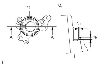
Using a sealer gun, apply seal packing in a continuous line as shown in the illustration.
- Seal packing:
Three Bond 1217G, 1217H or equivalent
- Standard seal diameter:
Within 1 mm (0.039 in.)
- NOTICE:
- ·
Install within 5 minutes of applying seal packing, and tighten the bolts within 15 minutes.
·Do not pour in engine oil for at least 2 hours after installation.
·Do not start the engine for at least 2 hours after installation.
·Do not allow seal packing to enter the engine oil passage.
| *A | A-A cross-section |
| *1 | Seal Packing |
| *a | Seal Application Position : Within 1 mm (0.039 in.) from Edge |
| *b | Seal Diameter : 2 to 4 mm (0.079 to 0.158 in.) |
Using a 6 mm hexagon wrench, install the pump drive case assembly with the 3 bolts.
- Torque:
- 19 N*m (194 kgf*cm, 14 ft.*lbf)
13751A
2.INSTALL VALVE LIFTER
Turn the crankshaft until the flat of the cam is facing the cylinder head cover's fuel pump attachment hole.
- HINT:
-
When installing the fuel pump by following the procedure described above, it is easier to install the fuel pump and the No. 2 fuel pipe later if the crankshaft ppointed side is not used to push up the pump activation surface.
Apply a coat of engine oil to the pump activation cam and pump lifter part.
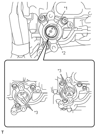
Apply new engine oil to the inside of the pump drive case assembly and the underside of the valve lifter, and install the valve lifter to the pump drive case assembly.
| *1 | Valve Lifter |
| *2 | Pump Drive Case Assembly |
| *3 | Location for applying new engine oil |
- HINT:
-
When applying oil to the underside of the valve lifter, drop a few drops of oil on the camshaft and the roller rocker arm from the valve lifter hole.
23100X
3.INSTALL FUEL PUMP ASSEMBLY
Apply a light coat of engine oil to a new O-ring and install it to the fuel pump assembly.
Using a "TORX" Plus Socket Wrench, install the fuel pump assembly with the 2 bolts.
- Torque:
- 21 N*m (214 kgf*cm, 16 ft.*lbf)
23807
4.CONNECT FUEL DELIVERY PIPE SUB-ASSEMBLY
Install the fuel delivery pipe sub-assembly to the fuel pump assembly with a new gasket and the union bolt.
- Torque:
- 31 N*m (316 kgf*cm, 23 ft.*lbf)
23815
5.INSTALL NO. 2 FUEL DELIVERY PIPE
17111
6.INSTALL INTAKE MANIFOLD