CRUISE CONTROL CRUISE CONTROL SYSTEM Clutch Switch Circuit
DESCRIPTION
Clutch switch circuit inspection is necessary for M/T vehicles.
When the clutch pedal is released, the ECM receives positive (+) battery voltage through the ECU IG2 fuse. While depressing the clutch pedal, the clutch switch sends a signal to terminal CLSW of the ECM. The ECM cancels cruise control drive when terminal CLSW receives the signal.
WIRING DIAGRAM
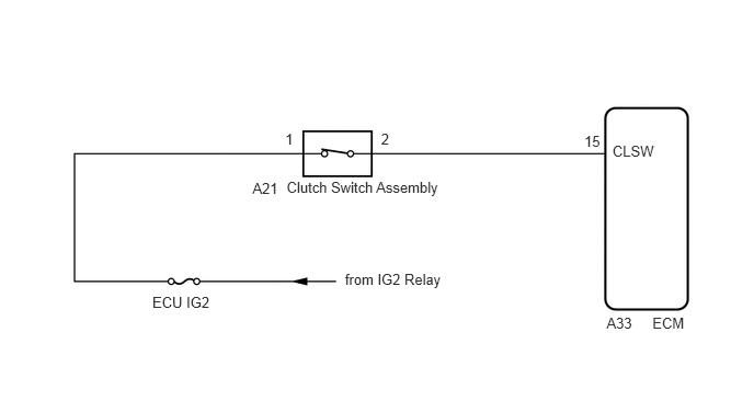
CAUTION / NOTICE / HINT
- HINT:
-
Clutch switch assembly conditions can be checked using the GTS.
- 1.
Connect the GTS to the DLC3.
2.Turn the ignition switch to ON.
3.Turn the GTS on.
4.Enter the following menus: Powertrain / Engine / Data List / All Data / Clutch Switch (See page Engine / Hybrid System>FA20 (ENGINE CONTROL)>SFI SYSTEM>DATA LIST / ACTIVE TEST).
Engine Clutch Pedal Operation Clutch Switch Depressed ON Released OFF
PROCEDURE
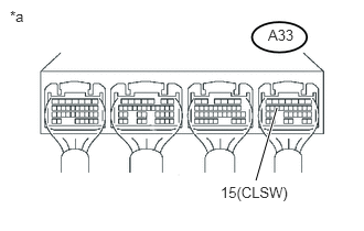
Turn the ignition switch to ON.
Measure the voltage according to the value(s) in the table below.
- Standard voltage:
Tester Connection Condition Specified Condition A33-15 (CLSW) - Body ground Clutch pedal depressed Below 1 V Clutch pedal released 11 to 14 V
| *a | Component with harness connected
(ECM) |
OK
NG
Inspect the clutch switch assembly (for LHD) (See page Drivetrain>CLUTCH>CLUTCH PEDAL SWITCH(for LHD)>INSPECTION).
Inspect the clutch switch assembly (for RHD) (See page Drivetrain>CLUTCH>CLUTCH PEDAL SWITCH(for RHD)>INSPECTION).
- Result:
Result Proceed to OK A NG (for LHD) B NG (for RHD) C
A
B
C
Disconnect the clutch switch assembly connector.
Disconnect the ECM connector.
Measure the resistance according to the value(s) in the table below.
- Standard resistance (Check for open):
Tester Connection Condition Specified Condition A33-15 (CLSW) - A21-2 Always Below 1 Ω
- Standard resistance (Check for short):
Tester Connection Condition Specified Condition A33-15 (CLSW) or A21-2 - Body ground Always 10 kΩ or higher
OK
NG