BRAKE CONTROL / DYNAMIC CONTROL SYSTEMS BRAKE ACTUATOR INSTALLATION
PROCEDURE

 1.INSTALL BRAKE ACTUATOR ASSEMBLY WITH BRAKE ACTUATOR BRACKET
Install the brake actuator assembly with brake actuator bracket using the 4 bolts.
- Torque:
- 33 N*m (338 kgf*cm, 24 ft.*lbf)
Connect the brake actuator connector to the brake actuator.
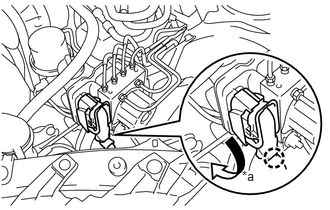
Turn the locking lever downwards, and engage the wire harness connector locking claw to lock the connector.
| *a | Turn |
- NOTICE:
- ·
Make sure that the actuator connector can be connected smoothly. Do not allow water, oil or dirt to enter.
·Make sure that the connector is locked securely.
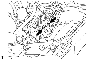
Using a union nut wrench 12 mm, tighten 2 brake tubes.
- Torque:
- 19 N*m (194 kgf*cm, 14 ft.*lbf)
- NOTICE:
-
Use the formula to calculate the special torque values for situations where the union nut wrench is combined with a torque wrench (See page Brake>BRAKE SYSTEM (OTHER)>BRAKE SYSTEM>PRECAUTION).
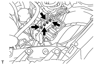
Using a union nut wrench 10 mm, tighten the 4 brake tubes.
- Torque:
- 15 N*m (155 kgf*cm, 11 ft.*lbf)
- NOTICE:
-
Use the formula to calculate the special torque values for situations where the union nut wrench is combined with a torque wrench (See page Brake>BRAKE SYSTEM (OTHER)>BRAKE SYSTEM>PRECAUTION).
Connect the front speed sensor LH harness clamp to the brake actuator bracket assembly.
Connect the cooler pipe to the clamp.
Connect the 2 harness clamp to the brake actuator bracket.
2.ADD BRAKE FLUID
3. BLEED BRAKE SYSTEM
4.INSPECT FLUID LEAK
5.INSPECT BRAKE FLUID LEVEL
53876A
6.INSTALL FRONT FENDER LINER LH
7.INSTALL FRONT WHEEL LH
- Torque:
- 120 N*m (1224 kgf*cm, 89 ft.*lbf)
8. VSC SENSOR NEUTRAL MEMORIZATION
9.INSPECT SPEED SENSOR