NETWORKING LIN COMMUNICATION SYSTEM B2786 No Response from Steering Lock ECU
DESCRIPTION
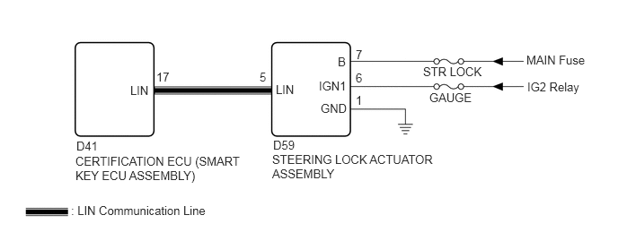
This DTC is stored when the communication between the certification ECU (smart key ECU assembly) and the steering lock actuator assembly stops for more than 10 seconds.
| DTC No. | DTC Detection Condition | Trouble Area |
|---|---|---|
| B2786 | This DTC is stored when communication between the certification ECU (smart key ECU assembly) and the steering lock actuator assembly stops for more than 10 seconds. | ·
Steering lock actuator assembly ·
Certification ECU (smart key ECU assembly) ·
Wire harness or connector |
WIRING DIAGRAM
CAUTION / NOTICE / HINT
- NOTICE:
- ·
When replacing the certification ECU (smart key ECU assembly) or steering lock actuator assembly (steering lock ECU), refer to the registration procedures for the Service Bulletin.
·When using the GTS to troubleshoot with the engine switch off:
Connect the GTS to the DLC3, and turn the courtesy switch on and off at 1.5-second intervals until communication between the GTS and vehicle begins.
·Inspect the fuses for circuits related to this system before performing the following inspection procedure.
- HINT:
-
When communication between the steering lock actuator assembly and certification ECU (smart key ECU assembly) stops, DTC B2785 is also stored.
PROCEDURE
Clear the DTC (See page Power Source / Network>NETWORKING>LIN COMMUNICATION SYSTEM>DTC CHECK / CLEAR).
NEXT
Check for DTC (See page Power Source / Network>NETWORKING>LIN COMMUNICATION SYSTEM>DTC CHECK / CLEAR).
| Result | Proceed to |
|---|---|
| DTC B2786 is output | A |
| DTC B2786 and B2785 is output | B |
A
B
Disconnect the D41 certification ECU (smart key ECU assembly) connector.
Disconnect the D59 steering lock actuator assembly connector.
Measure the resistance according to the value(s) in the table below.
- Standard Resistance (Check for Open):
Tester Connection Condition Specified Condition D41-17 (LIN) - D59-5 (LIN) Always Below 1 Ω
- Standard Resistance (Check for Short):
Tester Connection Condition Specified Condition D41-17 (LIN) or D59-5 (LIN) - Body ground Always 10 kΩ or higher
OK
NG
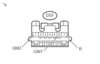
Measure the resistance according to the value(s) in the table below.
- Standard Resistance:
Tester Connection Condition Specified Condition D59-1 (GND) - Body ground Always Below 1 Ω
Measure the voltage according to the value(s) in the table below.
- Standard Voltage:
Tester Connection Switch Condition Specified Condition D59-6 (IGN1) - Body ground Engine Switch On (IG) 11 to 14 V D59-7 (B) - Body ground Always 11 to 14 V
| *a | Front view of wire harness connector
(to Steering Lock Actuator Assembly) |
OK
NG
Replace the steering lock actuator assembly. (See page Steering>STEERING COLUMN>STEERING COLUMN ASSEMBLY>REMOVAL)
NEXT
Clear the DTC (See page Power Source / Network>NETWORKING>LIN COMMUNICATION SYSTEM>DTC CHECK / CLEAR).
Recheck for DTCs.
| Result | Proceed to |
|---|---|
| DTC B2786 is not output | A |
| DTC B2786 is output | B |
A
B