THEFT DETERRENT / KEYLESS ENTRY ENTRY AND START SYSTEM(for Start Function) B2276 ACCR Signal Circuit Malfunction
DESCRIPTION
This DTC is stored when an input malfunction occurs in the ACC relay cut input signal circuit inside the certification ECU (smart key ECU assembly).
- HINT:
-
When the battery cable is disconnected and reconnected, the power source returns to the mode it was in before the battery cable was disconnected.
| DTC No. | DTC Detection Condition | Trouble Area | DTC Output Confirmation Operation |
|---|---|---|---|
| B2276 | When an input malfunction occurs in the ACC relay cut input signal circuit inside the certification ECU (smart key ECU assembly) (1-trip detection logic*) | ·
Certification ECU (smart key ECU assembly) ·
SFI system ·
Wire harness or connector |
Engine start operation is performed. |
*: Only output while a malfunction is present and the engine switch is on (IG)
| Vehicle Condition when Malfunction Detected | Fail-safe Function when Malfunction Detected |
|---|---|
·
ACC is not turned off during cranking. ·
The start assembly turns slowly. |
- |
| DTC No. | Data List Item | Active Test Item |
|---|---|---|
| B2276 | - | - |
WIRING DIAGRAM
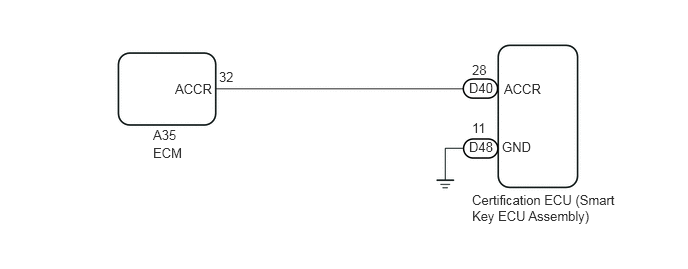
CAUTION / NOTICE / HINT
- NOTICE:
- ·
When using the GTS with the engine switch off to troubleshoot:
Connect the GTS to the DLC3 and turn a courtesy light switch on and off at 1.5-second intervals until communication between the GTS and vehicle begins.
·The entry and start system uses multiplex communication. First perform the inspections in "How to Proceed with Troubleshooting" to confirm that there are no communication malfunctions before proceeding with troubleshooting (See page Vehicle Interior>THEFT DETERRENT / KEYLESS ENTRY>ENTRY AND START SYSTEM (for Start Function)>HOW TO PROCEED WITH TROUBLESHOOTING).
·Before replacing the certification ECU (smart key ECU assembly), refer to the entry and start system (for Entry Function) (See page Vehicle Interior>THEFT DETERRENT / KEYLESS ENTRY>ENTRY AND START SYSTEM (for Entry Function)>PRECAUTION).
·After performing repairs, perform the operation that fulfills the DTC output confirmation operation, and then confirm that no DTCs are output again.
·Inspect the fuses of circuits related to this system before performing the following inspection procedure.
PROCEDURE
Disconnect the D40 and D48 certification ECU (smart key ECU assembly) connectors.
Disconnect the A35 ECM connector.
Measure the resistance according to the value(s) in the table below.
- Standard Resistance:
Tester Condition Connection Specified Condition D40-28 (ACCR) - A35-32 (ACCR) Always Below 1 Ω D48-11 (GND) - Body ground Always Below 1 Ω D40-28 (ACCR) - Body ground Always 10 kΩ or higher
OK
NG
Reconnect the D40 and D48 certification ECU (smart key ECU assembly) connectors.
Reconnect the A35 ECM connector.
Measure the voltage according to the value(s) in the table below.
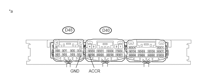
| *a | Component with harness connected
(Certification ECU (Smart Key ECU Assembly)) |
- | - |
- Standard Voltage:
Tester Condition Connection Specified Condition D40-28 (ACCR) - D48-11 (GND)*1 With the brake pedal*1 or clutch pedal*2 depressed, the engine switch is pressed and held (starter on) → After approx. 1 sec. has elapsed, the engine switch is released (starter off) 2 V or less → 9 V or higher
*1: for Automatic Transmission
*2: for Manual Transmission
OK
NG