Home › Vehicle Interior › THEFT DETERRENT / KEYLESS ENTRY › THEFT DETERRENT SYSTEM
RM2090E _58 Vehicle Interior _060697 THEFT DETERRENT / KEYLESS ENTRY _0297683 THEFT DETERRENT SYSTEM J

THEFT DETERRENT / KEYLESS ENTRY  THEFT DETERRENT SYSTEM  Horn Circuit  


DESCRIPTION

When the theft deterrent system is switched from the armed state to the alarm sounding state, the main body ECU (network gateway ECU) transmits a signal to cause the horn to sound at 0.4 second intervals.

WIRING DIAGRAM
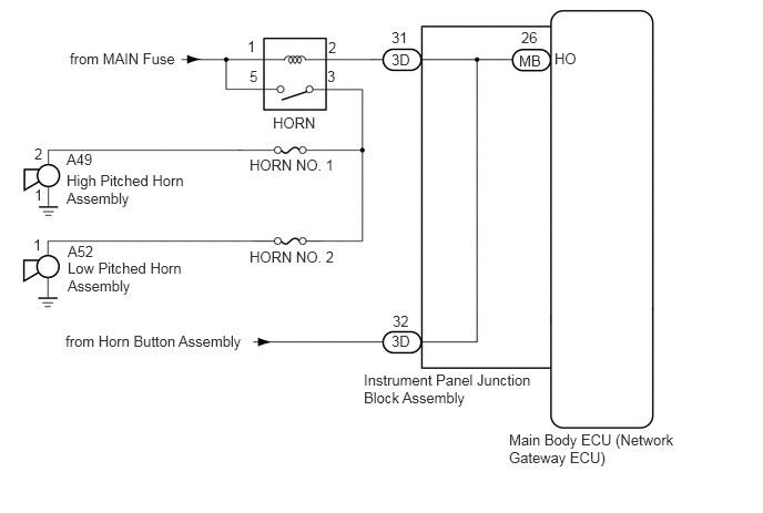
B316996E02
3.417,3.49 5.042,3.833 1.625,0.344 10 false Instrument Panel Junction Block Assembly 4.781,4.052 6.417,4.417 1.635,0.365 10 false Main Body ECU (Network Gateway ECU) 5.208,0.469 5.5,0.615 0.292,0.146 10 false HO 4.875,0.49 5.115,0.635 0.24,0.146 10 false MB 4.896,0.271 5.083,0.417 0.188,0.146 10 false 26 3.677,3.125 3.885,3.271 0.208,0.146 10 false 3D 3.688,2.938 3.875,3.083 0.188,0.146 10 false 32 3.677,0.479 3.875,0.635 0.198,0.156 10 false 3D 3.677,0.271 3.865,0.417 0.188,0.146 10 false 31 0.656,0.469 1.719,0.646 1.063,0.177 10 false from MAIN Fuse 0.635,2.438 1.75,2.813 1.115,0.375 10 false Low Pitched Horn Assembly 0.625,1.615 1.771,1.969 1.146,0.354 10 false High Pitched Horn Assembly 2.563,1.073 3.01,1.229 0.448,0.156 10 false HORN 2.344,2.333 3.219,2.49 0.875,0.156 10 false HORN NO. 2 2.344,1.469 3.219,1.625 0.875,0.156 10 false HORN NO. 1 0.635,2.281 0.948,2.448 0.313,0.167 10 false A52 0.625,1.417 0.938,1.583 0.313,0.167 10 false A49 0.615,3.125 2.333,3.333 1.719,0.208 10 false from Horn Button Assembly 0.323,1.365 0.438,1.51 0.115,0.146 10 false 2 0.313,2.219 0.427,2.365 0.115,0.146 10 false 1 0.323,1.75 0.438,1.896 0.115,0.146 10 false 1 3.073,0.635 3.208,0.813 0.135,0.177 10 false 3 2.344,0.635 2.49,0.813 0.146,0.177 10 false 5 3.083,0.365 3.229,0.542 0.146,0.177 10 false 2 2.323,0.354 2.469,0.531 0.146,0.177 10 false 1

CAUTION / NOTICE / HINT

NOTICE:

Inspect the fuses for circuits related to this system before performing the following inspection procedure.


PROCEDURE

1.INSPECT HORNS
a.

Press the horn switch and check if the horns sound.

Result
Result Proceed to
Horns sound A
Horns do not sound B


A

2.PERFORM ACTIVE TEST USING GTS

B

2.PERFORM ACTIVE TEST USING GTS
a.

Connect the GTS to the DLC3.


b.

Turn the engine switch on (IG).


c.

Turn the GTS on.


d.

Enter the following menus: Body Electrical / Main Body / Active Test.


e.

According to the display on the GTS, perform the Active Test.

Main Body
Tester Display Test Part Control Range Diagnostic Note
Vehicle Horn Vehicle horns ON/OFF -

OK:

The vehicle horns sound and stop correctly when operating them through the GTS.


OK

REPLACE MAIN BODY ECU (NETWORK GATEWAY ECU)

NG

3.INSPECT INSTRUMENT PANEL JUNCTION BLOCK ASSEMBLY
a.

Remove the instrument panel junction block assembly (See page Power Source / Network>POWER DISTRIBUTION>MAIN BODY ECU>REMOVAL).


b.

Remove the main body ECU (network gateway ECU) from the instrument panel junction block assembly.


c.

Measure the resistance according to the value(s) in the table below.
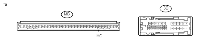
U190259E01
0.112,0.058 0.298,0.219 0.186,0.161 10 *a 2.213,0.403 2.464,0.560 0.251,0.156 10 MB 5.659,0.197 5.869,0.353 0.210,0.156 10 3D 3.341,1.176 3.600,1.340 0.259,0.165 10 HO 3.362,0.927 3.435,1.16 false

Standard Resistance:
Tester Connection Condition Specified Condition
MB-26 (HO) - 3D-31 Always Below 1 Ω
MB-26 (HO) - 3D-32 Always Below 1 Ω


Text in Illustration
*a Component without harness connected
(Instrument Panel Junction Block Assembly)
- -


OK

REPLACE MAIN BODY ECU (NETWORK GATEWAY ECU)

NG

REPLACE INSTRUMENT PANEL JUNCTION BLOCK ASSEMBLY