Home › Vehicle Interior › THEFT DETERRENT / KEYLESS ENTRY › ENGINE IMMOBILISER SYSTEM(w/o Entry and Start System)
RM2090E _58 Vehicle Interior _060697 THEFT DETERRENT / KEYLESS ENTRY _0297684 ENGINE IMMOBILISER SYSTEM(w/o Entry and Start System) C

THEFT DETERRENT / KEYLESS ENTRY  ENGINE IMMOBILISER SYSTEM(w/o Entry and Start System)  B1409  SCU Communication Circuit  


DESCRIPTION

The main body ECU (network gateway ECU) stores this code if a communication problem is detected between the main body ECU (network gateway ECU) and the transponder key ECU assembly.

DTC Code DTC Detection Condition Trouble Area
B1409 When there is a problem in communication between the main body ECU (network gateway ECU) and the transponder key ECU assembly.
·

Harness or connector

·

Main body ECU (network gateway ECU)

·

Transponder key ECU assembly


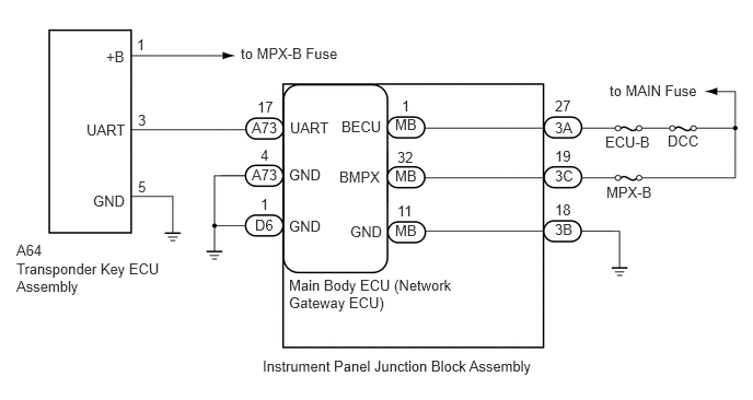
WIRING DIAGRAM

B317021E02
2.5,3.406 5.167,3.719 2.667,0.313 10 false Instrument Panel Junction Block Assembly 2.75,2.635 4.427,3.281 1.677,0.646 10 false Main Body ECU (Network Gateway ECU) 3.76,2.115 4,2.271 0.24,0.156 10 false MB 3.76,1.594 4,1.75 0.24,0.156 10 false MB 5.281,2.104 5.521,2.26 0.24,0.156 10 false 3B 5.281,1.594 5.521,1.75 0.24,0.156 10 false 3C 5.281,1.135 5.521,1.292 0.24,0.156 10 false 3A 3.76,1.104 4,1.26 0.24,0.156 10 false MB 6.354,1.26 6.698,1.417 0.344,0.156 10 false DCC 5.771,1.75 6.229,1.906 0.458,0.156 10 false MPX-B 5.76,1.271 6.219,1.427 0.458,0.156 10 false ECU-B 5.802,0.781 6.708,1.094 0.906,0.313 10 false to MAIN Fuse 2.427,2.063 2.667,2.219 0.24,0.156 10 false D6 2.396,1.583 2.677,1.74 0.281,0.156 10 false A73 2.396,1.135 2.677,1.292 0.281,0.156 10 false A73 0.156,2.302 0.438,2.458 0.281,0.156 10 false A64 0.156,2.479 1.615,3.125 1.458,0.646 10 false Transponder Key ECU Assembly 0.823,1.156 1.24,1.313 0.417,0.156 10 false UART 0.885,1.833 1.24,1.99 0.354,0.156 10 false GND 1.313,1.698 1.427,1.854 0.115,0.156 10 false 5 1.313,1.063 1.427,1.219 0.115,0.156 10 false 3 1.302,0.344 1.406,0.5 0.104,0.156 10 false 1 2.448,0.938 2.646,1.094 0.198,0.156 10 false 17 2.479,1.865 2.583,2.021 0.104,0.156 10 false 1 2.479,1.396 2.583,1.552 0.104,0.156 10 false 4 3.823,0.927 3.927,1.083 0.104,0.156 10 false 1 3.781,1.927 3.979,2.083 0.198,0.156 10 false 11 3.781,1.417 3.979,1.573 0.198,0.156 10 false 32 5.281,1.917 5.479,2.073 0.198,0.156 10 false 18 5.281,1.406 5.479,1.563 0.198,0.156 10 false 19 5.281,0.927 5.479,1.083 0.198,0.156 10 false 27 2.292,0.427 3.302,0.74 1.01,0.313 10 false to MPX-B Fuse 1.01,0.458 1.229,0.615 0.219,0.156 10 false +B 2.76,1.135 3.177,1.292 0.417,0.156 10 false UART 2.75,1.583 3.104,1.74 0.354,0.156 10 false GND 2.75,2.073 3.104,2.229 0.354,0.156 10 false GND 3.333,2.125 3.688,2.281 0.354,0.156 10 false GND 3.25,1.125 3.677,1.281 0.427,0.156 10 false BECU 3.229,1.604 3.656,1.76 0.427,0.156 10 false BMPX

CAUTION / NOTICE / HINT

NOTICE:
·

If the main body ECU (network gateway ECU) or transponder key ECU assembly is replaced, refer to Service Bulletin.

·

Inspect the fuses for circuits related to this system before performing the following inspection procedure.


PROCEDURE

1.CHECK HARNESS AND CONNECTOR (INSTRUMENT PANEL JUNCTION BLOCK - BATTERY, BODY GROUND)
a.

Disconnect the A73 and D6 main body ECU (network gateway ECU) connectors.


b.

Disconnect the 3A, 3B and 3C instrument panel junction block assembly connectors.
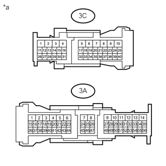

c.
U146922E05
0.063,0.063 0.25,0.219 0.188,0.156 10 false *a 1.625,0.24 1.833,0.396 0.208,0.156 10 false 3C 1.635,1.792 1.844,1.948 0.208,0.156 10 false 3A

Measure the voltage according to the value(s) in the table below.

Standard Voltage:
Tester Connection Condition Specified Condition
3A-27 - Body ground Always 11 to 14 V
3C-19 - Body ground Always 11 to 14 V


d.

Measure the resistance according to the value(s) in the table below.


Standard Resistance:
Tester Connection Condition Specified Condition
3B-18 - Body ground Always Below 1 Ω
A73-4 (GND) - Body ground Always Below 1 Ω
D6-1 (GND) - Body ground Always Below 1 Ω


Text in Illustration
*a Component without harness connected
(Instrument Panel Junction Block Assembly)


OK

2.INSPECT INSTRUMENT PANEL JUNCTION BLOCK ASSEMBLY

NG

REPAIR OR REPLACE HARNESS OR CONNECTOR

2.INSPECT INSTRUMENT PANEL JUNCTION BLOCK ASSEMBLY
a.

Remove the instrument panel junction block assembly (See page Power Source / Network>POWER DISTRIBUTION>MAIN BODY ECU>REMOVAL).


b.

Remove the main body ECU (network gateway ECU) from the instrument panel junction block assembly.


c.

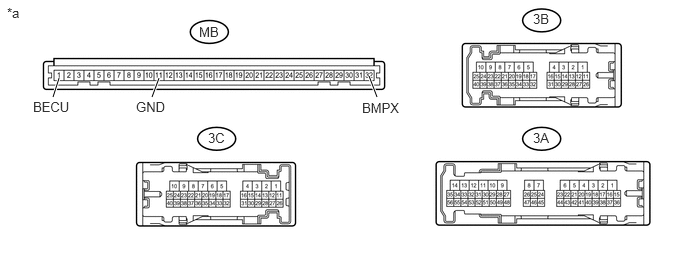
Measure the resistance according to the value(s) in the table below.


U190239E02
3.844,0.792 3.927,1.01 true 1.656,0.813 1.583,1.01 true 0.615,0.813 0.552,1.01 true 0.073,0.052 0.26,0.208 0.188,0.156 10 false *a 2.073,0.25 2.323,0.406 0.25,0.156 10 false MB 2.167,1.354 2.385,1.51 0.219,0.156 10 false 3C 5.552,1.354 5.771,1.51 0.219,0.156 10 false 3A 5.552,0.115 5.75,0.271 0.198,0.156 10 false 3B 3.771,1.042 4.208,1.208 0.438,0.167 10 false BMPX 1.417,1.031 1.76,1.188 0.344,0.156 10 false GND 0.344,1.031 0.76,1.188 0.417,0.156 10 false BECU

Text in Illustration
*a Component without harness connected
(Instrument Panel Junction Block Assembly)
- -

Standard Resistance:
Tester Connection Condition Specified Condition
MB-1 (BECU) - 3A-27 Always Below 1 Ω
MB-32 (BMPX) - 3C-19 Always Below 1 Ω
MB-11 (GND) - 3B-18 Always Below 1 Ω


OK

3.CHECK HARNESS AND CONNECTOR (TRANSPONDER KEY ECU ASSEMBLY - BATTERY, BODY GROUND)

NG

REPLACE INSTRUMENT PANEL JUNCTION BLOCK ASSEMBLY

3.CHECK HARNESS AND CONNECTOR (TRANSPONDER KEY ECU ASSEMBLY - BATTERY, BODY GROUND)
a.

Disconnect the A64 transponder key ECU assembly connector.


b.

Measure the voltage according to the value(s) in the table below.


Standard Voltage:
Tester Connection Condition Specified Condition
A64-1 (+B) - Body ground Always 11 to 14 V


c.

Measure the resistance according to the value(s) in the table below.


Standard Resistance:
Tester Connection Condition Specified Condition
A64-5 (GND) - Body ground Always Below 1 Ω


OK

4.CHECK HARNESS AND CONNECTOR (MAIN BODY ECU - TRANSPONDER KEY ECU ASSEMBLY)

NG

REPAIR OR REPLACE HARNESS OR CONNECTOR

4.CHECK HARNESS AND CONNECTOR (MAIN BODY ECU - TRANSPONDER KEY ECU ASSEMBLY)
a.

Measure the voltage and resistance according to the value(s) in the table below.


Standard Voltage:
Tester Connection Condition Specified Condition
A73-17 (UART) - Body ground Always Below 1 V


Standard Resistance:
Tester Connection Condition Specified Condition
A73-17 (UART) - A64-3 (UART) Always Below 1 Ω
A73-17 (UART) - Body ground Always 10 kΩ or higher


OK

5.REPLACE TRANSPONDER KEY ECU ASSEMBLY

NG

REPAIR OR REPLACE HARNESS OR CONNECTOR

5.REPLACE TRANSPONDER KEY ECU ASSEMBLY
a.

Replace the transponder key ECU assembly with a new one (Refer to Service Bulletin).


NEXT

6.CHECK FOR DTC
6.CHECK FOR DTC

OK

END (TRANSPONDER KEY ECU ASSEMBLY WAS DEFECTIVE)

NG

REPLACE MAIN BODY ECU (NETWORK GATEWAY ECU)