Home › Vehicle Interior › SUPPLEMENTAL RESTRAINT SYSTEMS › AIRBAG SYSTEM
RM2090E _58 Vehicle Interior _060701 SUPPLEMENTAL RESTRAINT SYSTEMS _0297704 AIRBAG SYSTEM D

SUPPLEMENTAL RESTRAINT SYSTEMS  AIRBAG SYSTEM  DIAGNOSIS SYSTEM  


FUNCTION OF SRS WARNING LIGHT


a.

Primary check

i.

Turn the ignition switch off. Wait for at least 2 seconds, then turn the ignition switch to ON. The SRS warning light comes on for approximately 6 seconds and the diagnosis of the airbag system (including the seat belt pretensioners) is performed.

HINT:

If malfunctions are detected during the primary check, the SRS warning light remains on even after the primary check period of approximately 6 seconds.


b.

Constant check

i.

After the primary check, the airbag ECU assembly constantly monitors the airbag system for malfunctions.

HINT:

If malfunctions are detected during the constant check, the airbag ECU assembly functions as follows:

·

The SRS warning light comes on.

·

The SRS warning light goes off, and then comes on. This indicates a source voltage drop. The SRS warning light goes off 10 seconds after the source voltage returns to normal.


c.

Review

i.

When the airbag system is normal:

The SRS warning light comes on only during the primary check period of approximately 6 seconds after the ignition switch is turned to ON.


ii.

When the airbag system is malfunctioning:

·

The SRS warning light remains on even after the primary check period.

·

The SRS warning light goes off after the primary check, but comes on again during the constant check.

·

The SRS warning light does not come on when turning the ignition switch from off to ON.


HINT:

The airbag ECU assembly keeps the SRS warning light on if airbags have been deployed.


SRS WARNING LIGHT CHECK

a.
C093955

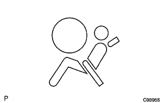
Turn the ignition switch to ON, and check that the SRS warning light comes on for approximately 6 seconds (primary check).


b.

Check that the SRS warning light goes off approximately 6 seconds after the ignition switch is turned to ON (constant check).

HINT:

When any of the following symptoms occur, refer to Problem Symptoms Table (See page Vehicle Interior>SUPPLEMENTAL RESTRAINT SYSTEMS>AIRBAG SYSTEM>PROBLEM SYMPTOMS TABLE).

·

The SRS warning light comes on occasionally after the primary check period.

·

The SRS warning light comes on, but a DTC is not output.

·

The ignition switch is turned from off to ON, but the SRS warning light does not come on.


FUNCTION OF PASSENGER AIRBAG ON/OFF INDICATOR


a.

Initial check

i.

Turn the ignition switch to ON.


ii.

The passenger airbag ON/OFF indicator comes on for approximately 6 seconds, then goes off for approximately 2 seconds.
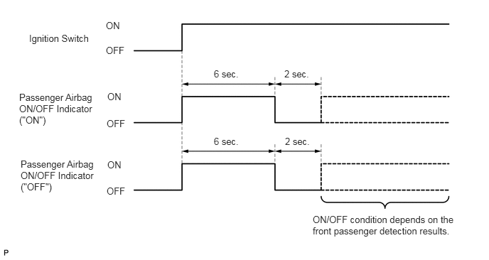
C370644E01
0.427,0.479 1.542,0.792 1.115,0.313 10 false Ignition Switch 0.281,1.344 1.531,1.917 1.25,0.573 10 false Passenger Airbag ON/OFF Indicator ("ON") 0.302,2.323 1.552,2.896 1.25,0.573 10 false Passenger Airbag ON/OFF Indicator ("OFF") 4.583,3.135 6.802,3.604 2.219,0.469 10 false ON/OFF condition depends on the front passenger detection results. 3.135,1 3.583,1.219 0.448,0.219 10 false 6 sec. 3.135,1.99 3.583,2.208 0.448,0.219 10 false 6 sec. 4.167,1 4.615,1.219 0.448,0.219 10 false 2 sec. 4.177,1.99 4.625,2.208 0.448,0.219 10 false 2 sec. 1.552,0.292 2,0.51 0.448,0.219 10 false ON 1.552,0.656 2,0.875 0.448,0.219 10 false OFF 1.573,1.333 2.021,1.552 0.448,0.219 10 false ON 1.573,2.333 2.021,2.552 0.448,0.219 10 false ON 1.563,1.729 2.01,1.948 0.448,0.219 10 false OFF 1.563,2.719 2.01,2.938 0.448,0.219 10 false OFF


iii.

Approximately 6 seconds after the ignition switch is turned to ON, the passenger airbag ON/OFF indicator will be ON/OFF depending on the conditions listed below.

Airbag Cut Off Switch Passenger Airbag ON/OFF Indicator SRS Warning Light
ON Indicator OFF Indicator
ON position ON OFF OFF
OFF position OFF ON OFF
Switch failure OFF ON ON

HINT:

If the passenger airbag ON/OFF indicator does not operate as specified in the table according to the airbag cut off switch status, and the SRS warning light is off, no DTC will be output. Therefore, perform troubleshooting for Trouble in Passenger Airbag ON/OFF Indicator (See page Vehicle Interior>SUPPLEMENTAL RESTRAINT SYSTEMS>AIRBAG SYSTEM>Trouble in Passenger Airbag ON/OFF Indicator).


PASSENGER AIRBAG ON/OFF INDICATOR CHECK (WITH AIRBAG CUT-OFF SWITCH)
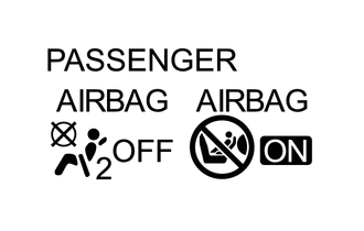

a.
C263384

Turn the ignition switch to ON.


b.

Check that the passenger airbag ON/OFF indicator ("ON" and "OFF") comes on for approximately 6 seconds, then goes off for approximately 2 seconds.

HINT:

Refer to the indicator operation table in the preceding step regarding the passenger airbag ON/OFF indicator when the ignition switch is turned to ON and approximately 6 seconds elapse.


FUNCTION OF SRS CONNECTORS


a.

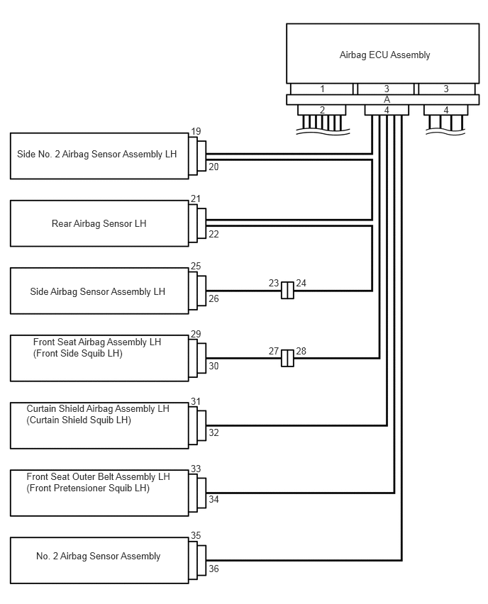
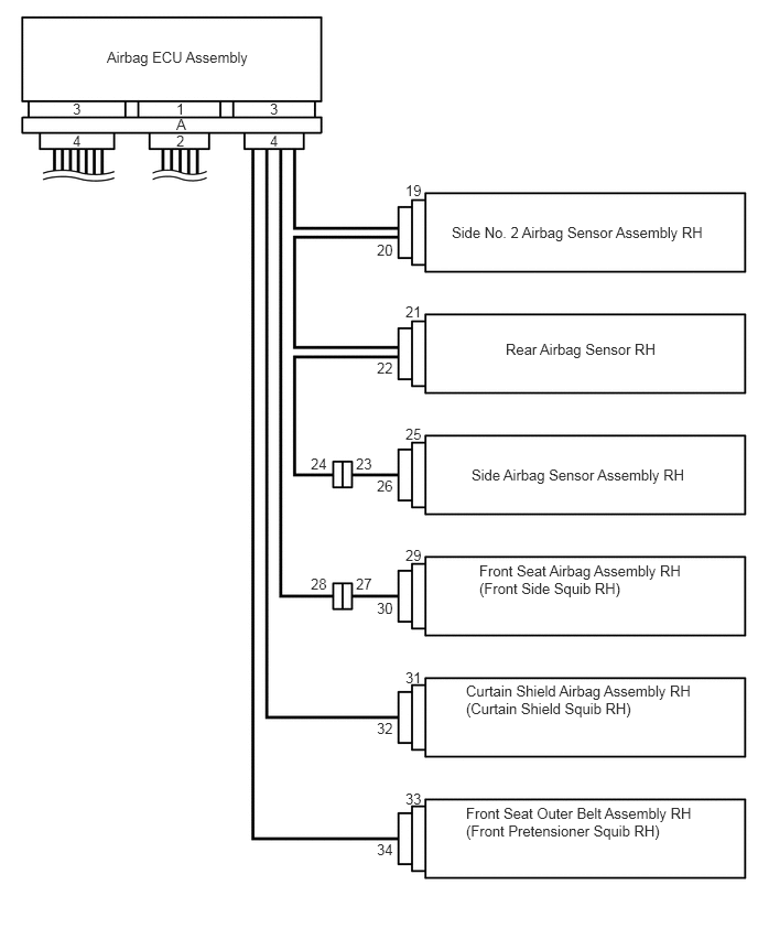
The SRS connectors are located as shown in the illustration.
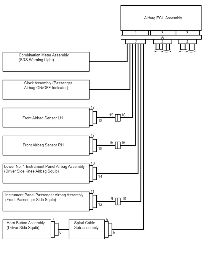
C263385E01
5.063,0.547 6.467,0.692 1.404,0.146 10 Airbag ECU Assembly 6.542,1.067 6.646,1.213 0.104,0.145 10 3 5.668,1.067 5.772,1.213 0.104,0.145 10 3 4.73,1.376 4.834,1.518 0.104,0.141 10 2 4.73,1.067 4.834,1.213 0.104,0.145 10 1 5.664,1.219 5.775,1.361 0.111,0.141 10 A 6.542,1.376 6.646,1.518 0.104,0.141 10 4 5.668,1.376 5.772,1.518 0.104,0.141 10 4 3.179,3.676 3.352,3.822 0.173,0.145 10 17 3.443,4.147 3.618,4.293 0.176,0.145 10 18 0.656,1.839 2.585,2.189 1.929,0.350 10 Combination Meter Assembly (SRS Warning Light) 0.789,4.048 2.584,4.197 1.795,0.150 10 Front Airbag Sensor LH 3.831,3.946 4.042,4.092 0.210,0.145 10 15 4.256,3.946 4.457,4.092 0.201,0.145 10 16 0.846,2.827 2.615,3.177 1.769,0.350 10 Clock Assembly (Passenger Airbag ON/OFF Indicator) 3.897,6.888 4.070,7.033 0.173,0.145 10 9 4.284,6.888 4.458,7.033 0.173,0.145 10 10 3.179,4.658 3.352,4.804 0.173,0.145 10 17 3.443,5.127 3.616,5.272 0.173,0.145 10 18 3.179,5.647 3.352,5.793 0.173,0.145 10 13 3.443,6.101 3.616,6.247 0.173,0.145 10 14 1.834,7.61 2.007,7.755 0.173,0.145 10 7 2.083,8.063 2.256,8.208 0.173,0.145 10 8 3.179,6.626 3.352,6.771 0.173,0.145 10 11 3.443,7.088 3.616,7.234 0.173,0.145 10 12 3.714,7.61 3.887,7.755 0.173,0.145 10 5 3.963,8.063 4.138,8.208 0.176,0.145 10 6 2.605,7.727 3.510,8.082 0.905,0.355 10 Spiral Cable Sub-assembly 0.146,5.754 3.123,6.203 2.977,0.449 10 Lower No. 1 Instrument Panel Airbag Assembly (Driver Side Knee Airbag Squib) 3.827,4.912 4.037,5.058 0.210,0.145 10 15 4.252,4.912 4.453,5.058 0.201,0.145 10 16 0.799,5.004 2.306,5.170 1.508,0.166 10 Front Airbag Sensor RH 0.184,6.747 3.160,7.196 2.977,0.449 10 Instrument Panel Passenger Airbag Assembly (Front Passenger Side Squib) 0.233,7.727 1.649,8.078 1.416,0.350 10 Horn Button Assembly (Driver Side Squib)

C263387E01
4.989,0.715 6.401,0.860 1.411,0.146 10 Airbag ECU Assembly 6.514,1.531 6.618,1.672 0.104,0.141 10 4 6.514,1.222 6.618,1.367 0.104,0.145 10 3 4.697,1.531 4.800,1.672 0.104,0.141 10 2 4.697,1.222 4.800,1.367 0.104,0.145 10 1 5.641,1.531 5.745,1.672 0.104,0.141 10 4 5.641,1.222 5.745,1.367 0.104,0.145 10 3 5.638,1.374 5.749,1.515 0.111,0.141 10 A 2.801,3.822 2.974,3.967 0.173,0.145 10 25 3.065,4.304 3.238,4.450 0.173,0.145 10 26 2.801,6.803 2.974,6.948 0.173,0.145 10 33 3.065,7.251 3.238,7.397 0.173,0.145 10 34 2.801,4.827 2.974,4.972 0.173,0.145 10 29 3.065,5.289 3.238,5.435 0.173,0.145 10 30 2.801,7.786 2.974,7.932 0.173,0.145 10 35 3.065,8.267 3.238,8.413 0.173,0.145 10 36 2.801,1.839 2.974,1.984 0.173,0.145 10 19 3.065,2.366 3.245,2.512 0.180,0.145 10 20 2.801,2.83 2.974,2.976 0.173,0.145 10 21 3.065,3.358 3.240,3.503 0.176,0.145 10 22 0.388,5.922 2.581,6.229 2.193,0.307 10 Curtain Shield Airbag Assembly LH (Curtain Shield Squib LH) 0.389,6.918 2.580,7.234 2.191,0.316 10 Front Seat Outer Belt Assembly LH (Front Pretensioner Squib LH) 0.531,8.084 2.441,8.231 1.910,0.147 10 No. 2 Airbag Sensor Assembly 0.25,2.175 2.751,2.318 2.501,0.143 10 Side No. 2 Airbag Sensor Assembly LH 0.487,4.937 2.776,5.249 2.289,0.311 10 Front Seat Airbag Assembly LH (Front Side Squib LH) 2.801,5.811 2.974,5.957 0.173,0.145 10 31 3.065,6.274 3.238,6.419 0.173,0.145 10 32 0.758,3.197 2.212,3.349 1.454,0.152 10 Rear Airbag Sensor LH 0.441,4.202 2.578,4.351 2.137,0.149 10 Side Airbag Sensor Assembly LH 3.946,4.076 4.120,4.222 0.173,0.145 10 23 4.348,4.076 4.521,4.222 0.173,0.145 10 24 3.946,5.068 4.120,5.213 0.173,0.145 10 27 4.348,5.068 4.521,5.213 0.173,0.145 10 28

C263389E02
1.01,0.458 2.417,0.75 1.406,0.292 10 false Airbag ECU Assembly 3.563,5.667 3.74,5.813 0.177,0.146 10 false 30 3.833,5.167 4.01,5.313 0.177,0.146 10 false 29 3.833,4.021 4.01,4.167 0.177,0.146 10 false 25 3.563,4.51 3.74,4.656 0.177,0.146 10 false 26 3.833,6.323 4.01,6.469 0.177,0.146 10 false 31 3.563,6.802 3.74,6.948 0.177,0.146 10 false 32 3.833,7.469 4.01,7.615 0.177,0.146 10 false 33 3.563,7.948 3.74,8.094 0.177,0.146 10 false 34 2.552,1.25 2.656,1.396 0.104,0.146 10 false 4 2.552,0.948 2.656,1.094 0.104,0.146 10 false 3 1.667,1.25 1.771,1.396 0.104,0.146 10 false 2 1.667,0.948 1.771,1.094 0.104,0.146 10 false 1 0.688,1.25 0.792,1.396 0.104,0.146 10 false 4 0.688,0.948 0.792,1.094 0.104,0.146 10 false 3 3.833,1.719 4.01,1.865 0.177,0.146 10 false 19 3.563,2.281 3.74,2.427 0.177,0.146 10 false 20 3.833,2.865 4.01,3.01 0.177,0.146 10 false 21 3.563,3.396 3.74,3.542 0.177,0.146 10 false 22 1.667,1.094 1.781,1.24 0.115,0.146 10 false A 4.406,6.448 6.625,6.906 2.219,0.458 10 false Curtain Shield Airbag Assembly RH (Curtain Shield Squib RH) 4.406,7.604 6.677,8.083 2.271,0.479 10 false Front Seat Outer Belt Assembly RH (Front Pretensioner Squib RH) 4.271,2.115 6.781,2.427 2.51,0.313 10 false Side No. 2 Airbag Sensor Assembly RH 4.531,5.313 6.552,5.792 2.021,0.479 10 false Front Seat Airbag Assembly RH (Front Side Squib RH) 4.781,3.219 6.302,3.479 1.521,0.26 10 false Rear Airbag Sensor RH 4.458,4.406 6.635,4.708 2.177,0.302 10 false Side Airbag Sensor Assembly RH 3.365,4.302 3.542,4.448 0.177,0.146 10 false 23 2.938,4.302 3.115,4.448 0.177,0.146 10 false 24 3.365,5.438 3.542,5.583 0.177,0.146 10 false 27 2.938,5.438 3.115,5.583 0.177,0.146 10 false 28

Connector Type Application
Terminal Twin-lock Mechanism Connectors 2, 4, 6, 9, 15, 23
Half Connection Prevention Mechanism Connectors 6, 10
Activation Prevention Mechanism Connectors 2, 4, 5, 7, 9, 11, 13, 27, 29, 31, 33
Connector Lock Mechanism (1) Connectors 8, 12, 32, 34
Connector Position Assurance Mechanism Connectors 16, 18, 20, 22, 23, 26, 36
Connector Lock Mechanism (2) Connector A
Improper Connection Prevention Lock Mechanism Connector A


b.

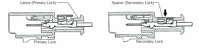
Terminal twin-lock mechanism

C190972E05
2.438,0.094 2.052,0.094 false 2.813,0.656 2.438,0.094 false 5.708,0.094 5.573,0.094 false 5.854,0.635 5.708,0.094 false 0.729,0.01 2.083,0.188 1.354,0.177 10 Lance (Primary Lock) 1.229,1.448 2.167,1.625 0.938,0.177 10 Primary Lock 4.021,0.01 5.698,0.188 1.677,0.177 10 Spacer (Secondary Lock) 4.896,1.427 5.948,1.604 1.052,0.177 10 Secondary Lock

i.

This mechanism is designed to increase the ability of the terminal to remain connected and prevent it from accidentally being disconnected.


ii.

The connector has a two-piece construction consisting of the housing and spacer to securely lock the terminal using both the lance (primary lock) and spacer (secondary lock).


c.

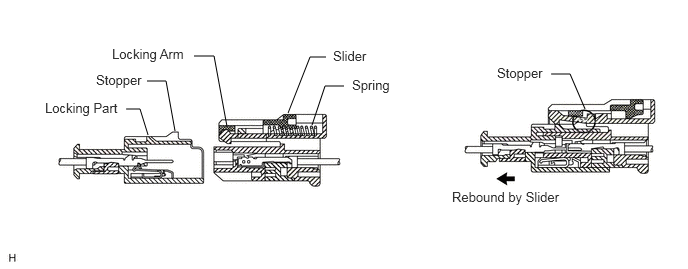
Half connection prevention mechanism

C147461E80
1.542,1.406 1.458,1.135 1.458,1.135 1.313,1.135 false 1.823,1.365 1.729,0.844 1.729,0.844 1.531,0.844 false 2.365,1.323 2.229,0.583 2.229,0.583 2.021,0.583 false 3,1.177 3.229,0.594 3.229,0.594 3.396,0.594 false 3.25,1.302 3.385,0.896 3.385,0.896 3.583,0.896 false 6.094,1.135 5.938,0.771 5.938,0.771 5.74,0.771 false 1.167,0.479 2.052,0.698 0.885,0.219 10 false Locking Arm 1,0.75 1.594,0.969 0.594,0.219 10 false Stopper 0.469,1.042 1.333,1.26 0.865,0.219 10 false Locking Part 3.469,0.5 3.906,0.688 0.438,0.188 10 false Slider 3.667,0.802 4.156,1.031 0.49,0.229 10 false Spring 5.177,0.677 5.76,0.865 0.583,0.188 10 false Stopper 4.708,1.969 6.042,2.156 1.333,0.188 10 false Rebound by Slider

i.

This mechanism is designed to prevent the connector from being connected only halfway.


ii.

If the connector is not completely connected, the connector is disconnected due to the spring force so that no continuity exists.


d.

Activation prevention mechanism

C261462E02
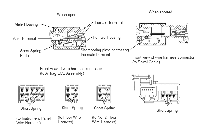
5.146,1.396 4.656,1.771 true 2.656,1.281 3.313,0.792 3.313,0.792 2.885,1.354 true 2.99,1.521 3.271,1.333 false 1.896,0.99 1.427,0.854 true 1.844,1.375 1.354,1.375 true 2.063,1.563 1.563,1.781 true 0.781,3.219 1.052,3.76 1.052,3.76 0.958,3.219 true 0.781,3.427 1.052,3.76 1.052,3.76 1.49,3.438 true 1.135,3.219 1.052,3.76 1.052,3.76 1.313,3.219 true 1.469,3.219 1.052,3.76 true 2.438,3.229 2.552,3.708 2.552,3.708 2.438,3.427 true 3.573,3.427 3.719,3.729 3.719,3.729 3.844,3.427 true 5.823,3.438 5.969,3.792 5.969,3.792 5.969,3.438 true 6.073,3.438 5.969,3.792 5.969,3.792 6.219,3.438 true 2.698,3.219 2.552,3.708 2.552,3.708 2.677,3.427 true 3.573,3.229 3.719,3.729 3.719,3.729 3.823,3.219 true 2.031,0.438 2.781,0.635 0.75,0.198 10 false When open 0.521,0.781 1.375,0.99 0.854,0.208 10 false Male Housing 0.438,1.292 1.333,1.479 0.896,0.188 10 false Male Terminal 0.719,1.729 1.531,2.083 0.813,0.354 10 false Short Spring Plate 3.313,1.25 4.375,1.469 1.063,0.219 10 false Female Housing 3.375,0.719 4.458,0.927 1.083,0.208 10 false Female Terminal 0.729,3.781 1.531,3.969 0.802,0.188 10 false Short Spring 0.583,4.135 1.854,4.479 1.271,0.344 10 false (to Instrument Panel Wire Harness) 2.063,4.104 2.927,4.458 0.865,0.354 10 false (to Floor Wire Harness) 3.281,4.104 4.25,4.479 0.969,0.375 10 false (to No. 2 Floor Wire Harness) 4.719,1.958 6.99,2.302 2.271,0.344 10 false Front view of wire harness connector: (to Spiral Cable) 5.302,0.344 6.208,0.531 0.906,0.188 10 false When shorted 2.875,1.698 4.635,2.063 1.76,0.365 10 false Short spring plate contacting the male terminal 1.427,2.365 3.719,2.729 2.292,0.365 10 false Front view of wire harness connector: (to Airbag ECU Assembly) 2.198,3.76 3,3.948 0.802,0.188 10 false Short Spring 3.354,3.771 4.156,3.958 0.802,0.188 10 false Short Spring 5.583,3.854 6.385,4.042 0.802,0.188 10 false Short Spring

i.

The activation prevention mechanism is designed to create a short circuit automatically between the positive and negative terminals of an airbag power source connector when disconnected.


ii.

The short spring plate contained in the connector creates a closed circuit on the airbag side (no potential difference can occur between both terminals), preventing accidental airbag deployment when servicing.


e.

Connector lock mechanism (1)

C147462E03
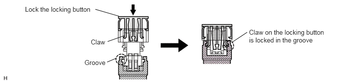
2.521,0.344 2.021,0.198 false 2.635,0.76 2.281,0.885 false 2.469,1.24 2.271,1.323 false 4.927,0.896 5.24,0.688 false 0.531,0.115 2.01,0.292 1.479,0.177 10 Lock the locking button 1.927,0.813 2.302,0.979 0.375,0.167 10 Claw 1.792,1.25 2.281,1.417 0.49,0.167 10 Groove 5.281,0.604 6.927,1.031 1.646,0.427 10 Claw on the locking button is locked in the groove

i.

This mechanism is designed to prevent the connector from accidentally being disconnected.


ii.

Locking the connector lock button engages the locking button claw to the groove on the other side connector to connect the connector securely.


f.

Connector Position Assurance (CPA) mechanism
C161464E04
0.854,0.198 1.021,0.198 false 0.833,1.104 0.854,0.198 false 1.052,0.479 1.219,0.479 false 0.927,1.25 1.052,0.479 false 0.729,2.292 0.958,2.292 false 0.51,1.792 0.729,2.292 false 5.635,0.781 5.469,0.781 false 5.646,1.156 5.635,0.781 false 1.063,0.125 2.271,0.354 1.208,0.229 10 Female Connector 1.26,0.406 2.094,0.656 0.833,0.25 10 Locking Part 1.0,2.219 2.042,2.469 1.042,0.25 10 Male Connector 2.958,0.302 4.542,0.573 1.583,0.271 10 Primary Lock Completed 5.073,0.302 6.844,0.573 1.771,0.271 10 Secondary Lock Completed 4.896,0.698 5.521,0.875 0.625,0.177 10 Retainer

i.

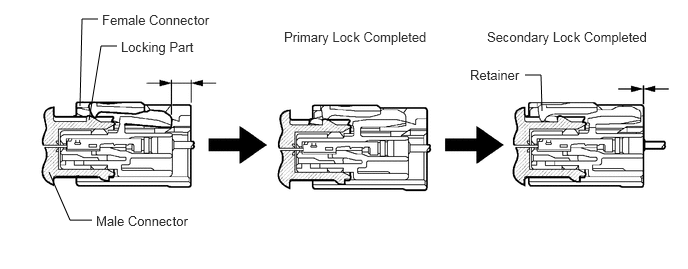
This mechanism is designed to detect when the connector is connected only halfway.


ii.

The CPA and female connector slide to the male connector side at the same time and the primary lock is completed when the female connector is engaged with the male connector. From this point, only the CPA slides to the male connector side and secondary lock is completed when the CPA retainer is engaged with the female connector. When the CPA and female connector ends are aligned, they are completely engaged.


g.

Connector lock mechanism (2)

C370646E02
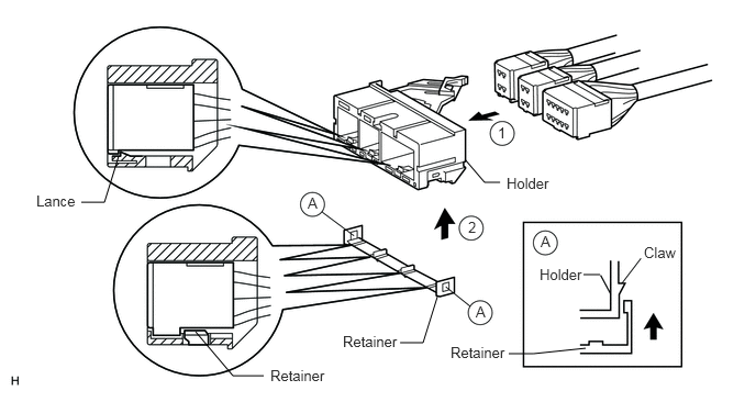
0.771,1.917 0.99,1.917 0.99,1.917 1.125,1.479 false 3.792,3.25 4.01,3.25 4.01,3.25 4.146,2.813 false 2.5,3.563 2.208,3.563 2.208,3.563 1.854,3.146 false 4.823,3.354 5.052,3.354 5.052,3.354 5.552,3.302 false 5.531,2.604 5.688,2.604 false 4.74,1.729 4.594,1.729 4.594,1.729 4.406,1.51 false 0.344,1.823 1.115,2.021 0.771,0.198 10 false Lance 2.563,3.479 3.333,3.677 0.771,0.198 10 false Retainer 3.25,3.156 4.021,3.354 0.771,0.198 10 false Retainer 4.271,3.26 5.042,3.458 0.771,0.198 10 false Retainer 4.802,1.656 5.573,1.854 0.771,0.198 10 false Holder 5.115,2.521 5.885,2.719 0.771,0.198 10 false Holder 6.104,2.313 6.875,2.51 0.771,0.198 10 false Claw 5.125,2.208 5.896,2.406 0.771,0.198 10 false A 4.51,2.875 5.281,3.073 0.771,0.198 10 false A 2.917,1.844 3.688,2.042 0.771,0.198 10 false A 4.719,1.177 5.49,1.375 0.771,0.198 10 false 1 4.438,2.073 5.208,2.271 0.771,0.198 10 false 2

i.

This mechanism is designed to prevent the connector from accidentally being disconnected.


ii.

Sliding the connector all the way into the holder and locking the lance completes the primary lock.


iii.

Engaging the retainer to the holder as shown in the illustration completes the secondary lock, preventing the connector from accidentally being disconnected.


h.

Improper connection prevention lock mechanism
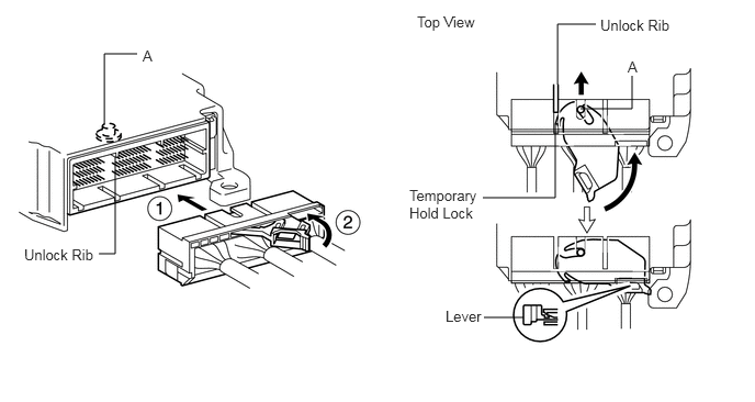
C204952E24
5.292,0.802 5.292,0.229 5.292,0.229 5.656,0.229 false 5.271,1.167 5.271,1.875 5.271,1.875 4.583,1.875 false 4.969,3.01 4.594,3.01 false 1.094,1.49 1.094,2.406 1.094,2.406 0.938,2.406 false 0.99,1.177 0.99,0.51 0.99,0.51 1.302,0.51 false 6,0.719 6,1.031 6,1.031 5.51,1.031 false 3.958,0.125 4.583,0.427 0.625,0.302 10 false Top View 0.229,2.333 0.927,2.573 0.698,0.24 10 false Unlock Rib 3.885,1.771 4.625,2.188 0.74,0.417 10 false Temporary Hold Lock 4.229,2.917 4.615,3.156 0.385,0.24 10 false Lever 5.698,0.156 6.448,0.406 0.75,0.25 10 false Unlock Rib 1.354,0.448 1.479,0.583 0.125,0.135 10 false A 5.958,0.552 6.115,0.698 0.156,0.146 10 false A

i.

This mechanism is designed to prevent the connector from being connected only halfway.


ii.

When the holder is connected to the airbag ECU assembly, the unlock rib unlocks the temporary hold lock, allowing the lever to be pushed in by rotating around the axis A.


iii.

Locking the lever to the holder locks the holder securely.


ACTIVATION PREVENTION MECHANISM


a.

Function of activation prevention mechanism

i.

An activation prevention mechanism is built into the connector (on the airbag ECU assembly side) of the airbag system squib circuit to prevent accidental airbag activation.


ii.

This mechanism closes the circuit when the connector is disconnected by bringing the short spring into contact with the terminals and insulating the circuit from external power sources to prevent accidental airbag activation.


b.

Releasing of activation prevention mechanism

i.

To release the activation prevention mechanism, insert a piece of paper with the same thickness as the male terminal (approximately 0.5 mm (0.0197 in.)) between the terminals and short spring to break the connection.


ii.

Refer to the following illustrations concerning connectors utilizing the activation prevention mechanism and its release method.

CAUTION:

Never release the activation prevention mechanism on the squib connector even when inspecting with the squib disconnected.


NOTICE:
·

Do not release the activation prevention mechanism unless specially directed by the troubleshooting procedure.

·

To prevent the terminal and short spring from being damaged, always use a piece of paper with the same thickness as the male terminal.
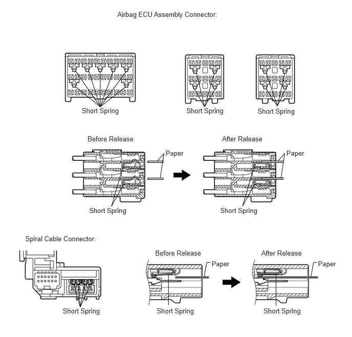


C263391E01
2.389,0.209 4.502,0.356 2.113,0.147 10 Airbag ECU Assembly Connector: 0.516,4.776 2.038,4.918 1.522,0.142 10 Spiral Cable Connector: 1.665,2.17 2.460,2.312 0.795,0.142 10 Short Spring 1.816,4.193 2.610,4.335 0.795,0.142 10 Short Spring 1.278,6.243 2.073,6.385 0.795,0.142 10 Short Spring 5.245,2.175 6.040,2.317 0.795,0.142 10 Short Spring 3.794,2.17 4.589,2.312 0.795,0.142 10 Short Spring 1.541,1.765 2.04,2.17 2.04,2.17 2.561,1.765 false 1.807,1.448 2.04,2.17 2.04,2.17 1.541,1.448 false 2.306,1.448 2.04,2.17 2.04,2.17 2.041,1.448 false 2.572,1.448 2.04,2.17 false 5.417,1.805 5.647,2.156 5.647,2.156 5.817,1.805 false 5.42,1.487 5.647,2.156 5.647,2.156 5.796,1.487 false 3.954,1.8 4.163,2.17 4.163,2.17 4.39,1.8 false 4.001,1.482 4.163,2.17 4.163,2.17 4.366,1.482 false 1.782,2.735 2.762,2.873 0.980,0.137 10 Before Release 4.521,2.735 5.408,2.873 0.887,0.137 10 After Release 3.372,3.032 3.773,3.174 0.401,0.142 10 Paper 3.206,3.267 3.337,3.123 3.337,3.123 3.262,3.613 false 5.831,3.032 6.232,3.174 0.401,0.142 10 Paper 5.665,3.267 5.796,3.123 5.796,3.123 5.721,3.613 false 2.508,3.378 2.27,4.193 2.27,4.193 2.523,3.735 false 4.484,4.193 5.279,4.335 0.795,0.142 10 Short Spring 3.193,6.243 3.988,6.385 0.795,0.142 10 Short Spring 3.159,5.066 4.139,5.204 0.980,0.137 10 Before Release 5.32,5.066 6.207,5.204 0.887,0.137 10 After Release 4.308,5.281 4.709,5.423 0.401,0.142 10 Paper 6.475,5.281 6.876,5.423 0.401,0.142 10 Paper 5.366,6.243 6.161,6.385 0.795,0.142 10 Short Spring 5.177,3.378 4.938,4.193 4.938,4.193 5.192,3.735 false 1.497,5.774 1.632,6.243 1.632,6.243 1.847,5.774 false 1.595,5.774 1.632,6.243 1.632,6.243 1.732,5.774 false 3.43,5.575 3.43,6.204 false 5.62,5.571 5.62,6.215 false 4.156,5.621 4.209,5.336 4.209,5.336 4.28,5.336 false 6.331,5.621 6.384,5.336 6.384,5.336 6.455,5.336 false