SUPPLEMENTAL RESTRAINT SYSTEMS AIRBAG SYSTEM B161A Lost Communication with Front Satellite Sensor Bus
DESCRIPTION
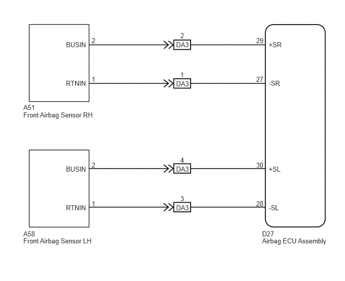
The front collision sensor circuit (front airbag sensor RH circuit and front airbag sensor LH circuit) is composed of the airbag ECU assembly, front airbag sensor RH and front airbag sensor LH.
The front airbag sensor RH and front airbag sensor LH detect impacts to the vehicle and send signals to the airbag ECU assembly to determine if the airbag should be deployed.
DTC B161A is stored when a malfunction is detected in the front collision sensor circuit (front airbag sensor RH circuit and front airbag sensor LH circuit).
| DTC No. | DTC Detection Condition | Trouble Area |
|---|---|---|
| B161A | ·
The airbag ECU assembly receives a line short circuit signal, an open circuit signal, a short circuit to ground signal or a short circuit to B+ signal in the front collision sensor circuit (front airbag sensor RH circuit and front airbag sensor LH circuit). ·
Front airbag sensor RH malfunction ·
Front airbag sensor LH malfunction ·
Airbag ECU assembly malfunction |
·
Instrument panel wire ·
Engine room main wire ·
Front airbag sensor RH ·
Front airbag sensor LH ·
Airbag ECU assembly |
WIRING DIAGRAM
PROCEDURE
Turn the ignition switch to ON, and wait for at least 60 seconds.
Turn the ignition switch off.
- HINT:
-
If a communication error occurs, DTCs for both the LH and RH sides will be stored simultaneously. To identify the malfunctioning area, turn the ignition switch off and then to ON again.
Turn the ignition switch to ON, and wait for at least 60 seconds.
Check for DTCs (See page Vehicle Interior>SUPPLEMENTAL RESTRAINT SYSTEMS>AIRBAG SYSTEM>DTC CHECK / CLEAR).
- Result:
Result Proceed to DTCs B1613 and B1618 are not output. A DTC B1613 is output. B DTC B1618 is output. C
- HINT:
- ·
DTCs indicating communication errors will be changed to DTCs indicating errors in initialization by turning the ignition switch off and then to ON again.
·Codes other than DTCs B1613 and B1618 may be output at this time, but they are not related to this check.
A
B
C
Clear the DTCs stored in memory (See page Vehicle Interior>SUPPLEMENTAL RESTRAINT SYSTEMS>AIRBAG SYSTEM>DTC CHECK / CLEAR).
Turn the ignition switch off.
Turn the ignition switch to ON, and wait for at least 60 seconds.
Check for DTCs (See page Vehicle Interior>SUPPLEMENTAL RESTRAINT SYSTEMS>AIRBAG SYSTEM>DTC CHECK / CLEAR).
- OK:
DTC B161A is not output.
- HINT:
-
Codes other than DTC B161A may be output at this time, but they are not related to this check.
OK
(See pageGeneral>INTRODUCTION>HOW TO TROUBLESHOOT ECU CONTROLLED SYSTEMS>HOW TO PROCEED WITH TROUBLESHOOTING)
NG