LIGHTING (EXT) STOP LIGHT SWITCH ADJUSTMENT
PROCEDURE

 84340
1.CHECK THE DATA LIST FOR STOP LIGHT SWITCH ASSEMBLY
Turn the ignition switch off.
Connect the GTS to the DLC3.
Turn the ignition switch to ON.
Enter the following menus: Chassis / ABS/VSC/TRC / Data List / Stop Light SW and Master Cylinder Pressure Sensor 1.
Without the brake pedal depressed, check that the Data List "Stop Light SW" is "OFF."
- HINT:
-
If the Data List display is "ON", check and adjust the stop light switch assembly installation position.
Depress the brake pedal slowly, and check that the Data List "Master Cylinder Pressure Sensor 1" is within the standard value when the Data List "Stop Light SW" is turned "ON".
- Standard pressure:
0.08 to 0.27 MPa(0.81 to 2.75 kgf/cm2, 11 to 39 psi)
- HINT:
-
If the Data List display is outside the standard value, check and adjust the stop light switch assembly installation position.
Check for DTCs.
- HINT:
-
If DTC C1249 is output, check and adjust the stop light switch assembly installation position.
84340
2.CHECK THE STROKE FROM THE POINT THAT THE STOP LIGHTS TURN ON
- HINT:
-
Measure the position (stroke distance of the brake pedal) of the brake pedal where the stop light switch assembly turns on (stop lights turn on).
Operate the tilt function and telescopic function of the steering column assembly so the steering wheel assembly is fully lowered and fully pushed in, and fixed in position.
Apply protective tape as shown in the illustration.
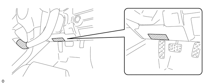

|
Protective Tape | - | - |
Pass the measuring tape through the steering wheel assembly and use adhesive tape to fasten it to the vertical center of the brake pedal.
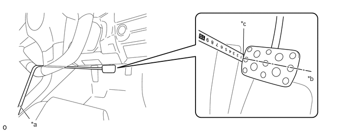
| *a | Measuring tape | *b | Vertical center of the brake pedal |
| *c | Fasten with adhesive tape | - | - |
- NOTICE:
-
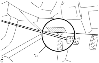 1.344,1.854 1.594,1.604 false 1.177,1.844 1.49,2.042 0.313,0.198 10 false *a
-
To accurately measure the brake pedal stroke, be sure that the No. 1 instrument panel under cover sub-assembly does not interfere with the measuring tape.
Text in Illustration *a No interference
Confirm the initial position of the brake pedal.
Extend the measuring tape straight out without depressing the brake pedal.
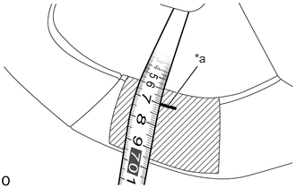
Use a pen to put a mark on the protective tape, and then read the distance on the measuring tape.
| *a | Mark |
|
|
Protective tape |
- HINT:
- ·
Put the mark at an easy to read digit on the scale, so the reference is easy to understand.
·As an example, the mark in the illustration is at 670 mm (26.38 in.).
Confirm the position at which the stop lights turn on.
While confirming whether the stop lights are on, gradually depress the brake pedal, and when the stop lights turn on, read the position on the measuring tape.
Calculate the stroke from the point (stroke distance of the brake pedal) that the stop lights turn on.
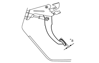
To calculate the stroke to the position that the stop lights turn on, subtract the value of the initial position from the value at which the stop lights turn on.
| *a | Stroke to position that stop lights turn on |
- Standard measurement:
6.0 to 8.0 mm (0.2362 to 0.3150 in.)
- HINT:
-
If the result is not as specified, check the condition of the installation of the stop light switch assembly, and adjust it.
84340
3.ADJUST STOP LIGHT SWITCH ASSEMBLY
Use the following procedure to adjust the stop light switch assembly so the stroke to the position (stroke distance of the brake pedal) at which the stop lights turn on is within the standard range. If finer adjustments are needed, then perform fine adjustments to the push rod of the brake booster assembly.
- Standard measurement (Standard range):
6.0 to 8.0 mm (0.2362 to 0.3150 in.)
- HINT:
- ·
The value read for the stroke to the position (stroke distance of the brake pedal) that the stop lights turn on includes 2.0 mm (0.0787 in.) of play at the brake pedal and push rod clevis.
·If the stroke to the position (stroke distance of the brake pedal) at which the stop lights turn on is less than 3.0 mm (0.1181 in.), the brake lights may come on, due to vibrations while driving, etc., even though the brakes are not operated.
Adjust at the stop light switch assembly.
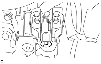
Use a pen to put a mark on the threads of the stop light switch assembly.
| *a | Mark |
Remove the stop light switch assembly.
Click hereVehicle Exterior>LIGHTING (EXT)>STOP LIGHT SWITCH>REMOVAL
Install the stop light switch assembly so that the distance to the mark on the threads changes.
- HINT:
- ·
For the distance of each thread pitch that the stop light switch assembly changes, the stroke to the position that the stop lights turn on changes by 4.0 mm (0.1575 in.) to 5.0 mm (0.1969 in.).
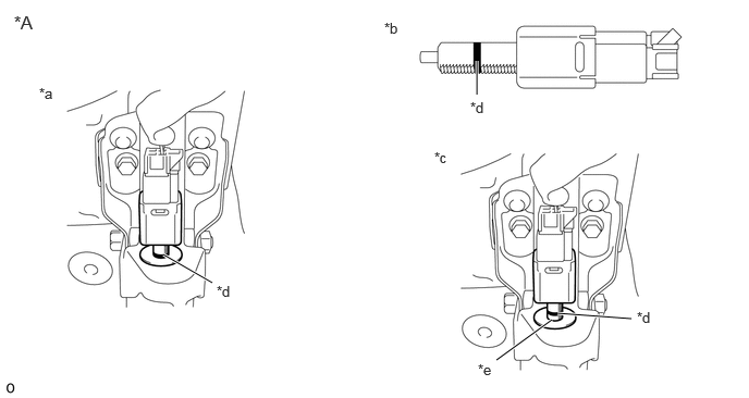 1.563,2.438 2.031,2.708 true 4.563,0.906 4.563,0.583 true 6.042,3.052 5.333,3 true 4.75,3.448 5.281,3.063 true 2.073,2.708 2.385,2.906 0.313,0.198 10 false *d 4.5,0.948 4.813,1.146 0.313,0.198 10 false *d 6.094,2.958 6.406,3.156 0.313,0.198 10 false *d 4.573,3.458 4.885,3.656 0.313,0.198 10 false *e 0.135,0.115 0.51,0.354 0.375,0.24 12 false *A 0.375,0.813 0.75,1.052 0.375,0.24 10 false *a 3.677,0.188 4.052,0.427 0.375,0.24 10 false *b 4.156,1.427 4.531,1.667 0.375,0.24 10 false *c
Text in Illustration *A Actual example of procedure - - *a Stop light switch assembly installed *b Stop light switch assembly removed *c Stop light switch assembly re-installed *d Mark *e Installed so separated by 2 thread pitches toward back of vehicle (near side) - -
·Pushing the stop light switch assembly towards the front of the vehicle (far side) retards the timing that the stop lights turn on. Pulling the stop light switch assembly towards the back of the vehicle (near side) advances the timing that the stop lights turn on.
Confirm that the stroke to the point (stroke distance of the brake pedal) that the stop lights turn on is within the specified range.
- Standard measurement:
6.0 to 8.0 mm (0.2362 to 0.3150 in.)
- HINT:
-
If the stroke to the position (stroke distance of the brake pedal) at which the stop lights turn on is not within the standard range and finer adjustments are needed, then perform fine adjustments to the push rod of the brake booster assembly.
Go to step (e) if the value is within the specified range.
Adjusting by the push rod of the brake booster assembly
Remove the stop light switch assembly.
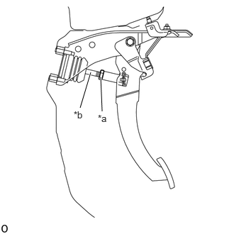
Loosen the push rod clevis lock nut of the brake booster assembly.
| *a | Clevis lock nut |
| *b | Push rod |
Rotate the push rod to adjust the stroke to the point (stroke distance of the brake pedal) that the stop lights turn on to be within the specified range.
Install the stop light switch assembly.
After securing the stop light switch assembly, confirm again that the stroke to the point (stroke distance of the brake pedal)) that the stop lights turn on is within the specified range.
- Standard measurement:
6.0 to 8.0 mm (0.2362 to 0.3150 in.)
Install the push rod clevis lock nut of the brake booster assembly.
- Torque:
- 19 N*m (194 kgf*cm, 14 ft.*lbf)
Pump the brakes and confirm that the stop lights turn on.
After adjusting, check the value for the "Master Cylinder Pressure Sensor 1" on the Data List.
Click hereVehicle Exterior>LIGHTING (EXT)>STOP LIGHT SWITCH>ADJUSTMENT
- HINT:
-
If the value is outside the standard value, brake fluid pressure may be generated even if the brake pedal is not depressed.
-
Click hereBrake>BRAKE SYSTEM (OTHER)>BRAKE SYSTEM>PROBLEM SYMPTOMS TABLE