Home › Vehicle Exterior › LIGHTING (EXT) › LIGHTING SYSTEM
RM2090E _59 Vehicle Exterior _060711 LIGHTING (EXT) _0297816 LIGHTING SYSTEM J

LIGHTING (EXT)  LIGHTING SYSTEM  Headlight Dimmer Switch Circuit  


DESCRIPTION

The main body ECU (network gateway ECU) receives the following signals:

·

Headlight dimmer switch tail, head, AUTO*1, high or high flash signal

·

Front fog light switch signal*2

·

Rear fog light switch signal*3

*1: w/ Automatic Light Control System

*2: w/ Front Fog Light

*3: w/ Rear Fog Light


WIRING DIAGRAM
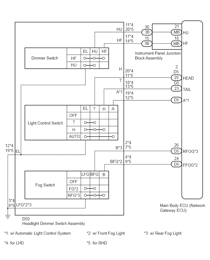
E252210E02
4.281,0.917 4.677,1.156 0.396,0.24 10 false 20*5 4.281,0.76 4.688,0.99 0.406,0.229 10 false 11*4 4.271,1.313 4.667,1.542 0.396,0.229 10 false 14*5 4.271,1.156 4.656,1.365 0.385,0.208 10 false 17*4 4.271,2.49 4.677,2.729 0.406,0.24 10 false 11*5 4.271,2.333 4.708,2.563 0.438,0.229 10 false 20*4 4.271,2.865 4.646,3.073 0.375,0.208 10 false 13*5 4.271,2.729 4.635,2.938 0.365,0.208 10 false 18*4 4.271,3.25 4.677,3.479 0.406,0.229 10 false 12*5 4.271,3.094 4.656,3.302 0.385,0.208 10 false 19*4 4.271,4.938 4.604,5.188 0.333,0.25 10 false 7*5 4.271,4.781 4.583,5.01 0.313,0.229 10 false 2*4 4.271,5.427 4.583,5.656 0.313,0.229 10 false 9*5 4.271,5.271 4.563,5.479 0.292,0.208 10 false 4*4 5.99,2.198 6.094,2.354 0.104,0.156 10 false 2 5.948,2.938 6.271,3.198 0.323,0.26 10 false 23 5.948,4.865 6.354,5.125 0.406,0.26 10 false 26 5.948,5.323 6.281,5.573 0.333,0.25 10 false 24 5.948,2.563 6.125,2.719 0.177,0.156 10 false 25 3.979,0.917 4.25,1.063 0.271,0.146 10 false HU 3.99,1.292 4.24,1.438 0.25,0.146 10 false HF 4.063,2.271 4.229,2.417 0.167,0.146 10 false H 4.073,2.667 4.219,2.813 0.146,0.146 10 false T 3.969,3.052 4.302,3.271 0.333,0.219 10 false A*1 3.948,4.958 4.271,5.167 0.323,0.208 10 false B*3 3.76,5.427 4.313,5.688 0.552,0.26 10 false BFG*2 5.927,2.365 6.125,2.51 0.198,0.146 10 false D5 5.938,2.75 6.135,2.896 0.198,0.146 10 false D5 5.938,3.323 6.135,3.469 0.198,0.146 10 false D5 5.938,5.073 6.135,5.219 0.198,0.146 10 false D5 5.938,5.521 6.135,5.667 0.198,0.146 10 false D5 5.958,0.813 6.135,0.969 0.177,0.156 10 false 21 5.948,1.219 6.135,1.365 0.188,0.146 10 false 18 5.927,1.01 6.156,1.156 0.229,0.146 10 false MB 6.24,1.031 6.677,1.333 0.438,0.302 10 false HU 6.24,1.396 6.677,1.698 0.438,0.302 10 false HF 6.24,2.583 6.677,2.885 0.438,0.302 10 false HEAD 6.24,2.969 6.677,3.271 0.438,0.302 10 false TAIL 6.24,3.344 6.677,3.646 0.438,0.302 10 false A*1 6.24,5.083 6.885,5.385 0.646,0.302 10 false RFOG*3 6.24,5.552 6.865,5.854 0.625,0.302 10 false FFOG*2 5.917,1.406 6.146,1.552 0.229,0.146 10 false MB 4.938,0.833 5.125,0.99 0.188,0.156 10 false 30 4.938,1.01 5.135,1.156 0.198,0.146 10 false 3B 4.938,1.219 5.125,1.375 0.188,0.156 10 false 15 4.927,1.396 5.125,1.542 0.198,0.146 10 false 3B 4.604,1.729 6.281,2.365 1.677,0.635 10 false Instrument Panel Junction Block Assembly 1.073,1.896 2.094,2.219 1.021,0.323 10 false Dimmer Switch 0.948,4.115 2.24,4.438 1.292,0.323 10 false Light Control Switch 1.208,6.229 2.021,6.552 0.813,0.323 10 false Fog Switch 5.458,6.927 7.146,7.594 1.688,0.667 10 false Main Body ECU (Network Gateway ECU) 0.76,7.542 3.01,7.885 2.25,0.344 10 false Headlight Dimmer Switch Assembly 0.146,7.875 2.563,8.219 2.417,0.344 10 false *1: w/ Automatic Light Control System 0.146,8.208 0.969,8.552 0.823,0.344 10 false *4: for LHD 2.958,8.208 3.781,8.552 0.823,0.344 10 false *5: for RHD 2.958,7.875 4.396,8.292 1.438,0.417 10 false *2: w/ Front Fog Light 4.917,7.875 6.323,8.313 1.406,0.438 10 false *3: w/ Rear Fog Light 0.76,7.385 1.052,7.531 0.292,0.146 10 false D50 3.135,1.667 3.385,1.854 0.25,0.188 10 false HU 2.833,1.667 3.073,1.844 0.24,0.177 10 false EL 2.833,3.615 3.073,3.823 0.24,0.208 10 false EL 2.365,3.854 2.719,4.042 0.354,0.188 10 false OFF 2.375,6.115 2.708,6.302 0.333,0.188 10 false OFF 2.781,5.865 3.094,6.094 0.313,0.229 10 false LFG 3.083,5.865 3.396,6.083 0.313,0.219 10 false BFG 3.5,5.875 3.698,6.073 0.198,0.198 10 false B 2.354,6.365 2.781,6.573 0.427,0.208 10 false FG*2 2.313,6.583 2.813,6.823 0.5,0.24 10 false RFG*3 2.354,4.573 2.802,4.771 0.448,0.198 10 false AUTO 2.479,4.083 2.677,4.271 0.198,0.188 10 false T 2.469,4.344 2.656,4.521 0.188,0.177 10 false H 3.469,1.667 3.719,1.854 0.25,0.188 10 false HF 2.427,1.906 2.656,2.083 0.229,0.177 10 false HF 2.417,2.135 2.656,2.313 0.24,0.177 10 false HU 3.177,3.625 3.417,3.844 0.24,0.219 10 false T 3.5,3.635 3.729,3.854 0.229,0.219 10 false H 3.813,3.625 4.021,3.854 0.208,0.229 10 false A 0.292,6.927 0.604,7.156 0.313,0.229 10 false 8*5 0.292,6.76 0.583,6.969 0.292,0.208 10 false 3*4 0.552,6.906 1.208,7.167 0.656,0.26 10 false LFG*2*3 0.177,5.052 0.49,5.281 0.313,0.229 10 false 19*5 0.177,4.885 0.531,5.094 0.354,0.208 10 false 12*4 0.531,5.083 1.083,5.344 0.552,0.26 10 false EL

PROCEDURE

1.READ VALUE USING GTS (HEADLIGHT DIMMER SWITCH ASSEMBLY)
a.

Connect the GTS to the DLC3.


b.

Turn the ignition switch to ON.


c.

Turn the GTS on.


d.

Enter the following menus: Body Electrical / Main Body / Data List.


e.

Read the display on the GTS.

Main Body
Tester Display Measurement Item/Range Normal Condition Diagnostic Note
Dimmer SW Dimmer switch high position signal / ON or OFF ON: Dimmer switch in high or high flash position
OFF: Dimmer switch in low position
-
Passing Light SW Dimmer switch high flash position (pass) signal / ON or OFF ON: Dimmer switch in high flash position
OFF: Dimmer switch not in high flash position
-
Rear Fog Light SW*3 Rear fog light switch signal / ON or OFF ON: Rear fog light switch on
OFF: Rear fog light switch off
-
Front Fog Light SW*2 Front fog light switch signal / ON or OFF ON: Front fog light switch on
OFF: Front fog light switch off
-
Auto Light SW*1 Light control switch AUTO position signal / ON or OFF ON: Light control switch in AUTO position
OFF: Light control switch not in AUTO position
-
Head Light SW (Head) Light control switch head position signal / ON or OFF ON: Light control switch in head position
OFF: Light control switch not in head position
-
Head Light SW (Tail) Light control switch tail position signal / ON or OFF ON: Light control switch in tail or head position
OFF: Light control switch in neither tail nor head position
-
Lighting Hi Light control switch head (Hi) position signal / ON or OFF ON: Headlight high beam on
OFF: Headlight high beam off
-

*1: w/ Automatic Light Control System

*2: w/ Front Fog Light

*3: w/ Rear Fog Light


OK:

The display is as specified in the normal condition column.


Result :
Result Proceed to
OK A
NG (Dimmer switch) B
NG (Fog switch and light control switch) C


A

REPLACE MAIN BODY ECU (NETWORK GATEWAY ECU)

B

2.INSPECT HEADLIGHT DIMMER SWITCH ASSEMBLY

C

4.INSPECT HEADLIGHT DIMMER SWITCH ASSEMBLY
2.INSPECT HEADLIGHT DIMMER SWITCH ASSEMBLY
a.

Remove the headlight dimmer switch assembly (See page Vehicle Exterior>LIGHTING (EXT)>HEADLIGHT DIMMER SWITCH>REMOVAL).


b.

Inspect the headlight dimmer switch assembly (See page Vehicle Exterior>LIGHTING (EXT)>HEADLIGHT DIMMER SWITCH>INSPECTION).


OK

3.CHECK HARNESS AND CONNECTOR (HEADLIGHT DIMMER SWITCH ASSEMBLY - JUNCTION BLOCK ASSEMBLY, BODY GROUND)

NG

REPLACE HEADLIGHT DIMMER SWITCH ASSEMBLY

3.CHECK HARNESS AND CONNECTOR (HEADLIGHT DIMMER SWITCH ASSEMBLY - JUNCTION BLOCK ASSEMBLY, BODY GROUND)
a.

Disconnect the 3B junction block assembly connector.


b.

Measure the resistance according to the value(s) in the table below.

Standard Resistance (Check for Open):
for LHD
Tester Connection Condition Specified Condition
D50-17 (HF) - 3B-15 Always Below 1 Ω
D50-11 (HU) - 3B-30 Always Below 1 Ω
D50-12 (EL) - Body ground Always Below 1 Ω

for RHD
Tester Connection Condition Specified Condition
D50-14 (HF) - 3B-15 Always Below 1 Ω
D50-20 (HU) - 3B-30 Always Below 1 Ω
D50-19 (EL) - Body ground Always Below 1 Ω


Standard Resistance (Check for Short):
for LHD
Tester Connection Condition Specified Condition
D50-17 (HF) - Body ground Always 10 kΩ or higher
D50-11 (HU) - Body ground*1 Always 10 kΩ or higher

for RHD
Tester Connection Condition Specified Condition
D50-14 (HF) - Body ground Always 10 kΩ or higher
D50-20 (HU) - Body ground*1 Always 10 kΩ or higher


OK

PROCEED TO NEXT SUSPECTED AREA SHOWN IN PROBLEM SYMPTOMS TABLE

NG

REPAIR OR REPLACE HARNESS OR CONNECTOR

4.INSPECT HEADLIGHT DIMMER SWITCH ASSEMBLY
a.

Remove the headlight dimmer switch assembly (See page Vehicle Exterior>LIGHTING (EXT)>HEADLIGHT DIMMER SWITCH>REMOVAL).


b.

Inspect the headlight dimmer switch assembly (See page Vehicle Exterior>LIGHTING (EXT)>HEADLIGHT DIMMER SWITCH>INSPECTION).


OK

5.CHECK HARNESS AND CONNECTOR (HEADLIGHT DIMMER SWITCH ASSEMBLY - MAIN BODY ECU (NETWORK GATEWAY ECU))

NG

REPLACE HEADLIGHT DIMMER SWITCH ASSEMBLY

5.CHECK HARNESS AND CONNECTOR (HEADLIGHT DIMMER SWITCH ASSEMBLY - MAIN BODY ECU (NETWORK GATEWAY ECU))
a.

Disconnect the D5 main body ECU (network gateway ECU) connector.


b.

Measure the resistance according to the value(s) in the table below.

Standard Resistance (Check for Open):
for LHD
Tester Connection Condition Specified Condition
D50-2 (B) - D5-26 (RFOG)*3 Always Below 1 Ω
D50-4 (BFG) - D5-24 (FFOG)*2 Always Below 1 Ω
D50-20 (H) - D5-2 (HEAD) Always Below 1 Ω
D50-19 (A) - D5-23 (A)*1 Always Below 1 Ω
D50-18 (T) - D5-25 (TAIL) Always Below 1 Ω
D50-12 (EL) - Body ground Always Below 1 Ω
D50-3 (LFG) - Body ground Always Below 1 Ω

for RHD
Tester Connection Condition Specified Condition
D50-7 (B) - D5-26 (RFOG)*3 Always Below 1 Ω
D50-9 (BFG) - D5-24 (FFOG)*2 Always Below 1 Ω
D50-11 (H) - D5-2 (HEAD) Always Below 1 Ω
D50-12 (A) - D5-23 (A)*1 Always Below 1 Ω
D50-13 (T) - D5-25 (TAIL) Always Below 1 Ω
D50-19 (EL) - Body ground Always Below 1 Ω
D50-8 (LFG) - Body ground Always Below 1 Ω


Standard Resistance (Check for Short):
for LHD
Tester Connection Condition Specified Condition
D50-2 (B)*3 - Body ground Always 10 kΩ or higher
D50-4 (BFG)*2 - Body ground Always 10 kΩ or higher
D50-20 (H) - Body ground Always 10 kΩ or higher
D50-19 (A)*1 - Body ground Always 10 kΩ or higher
D50-18 (T) - Body ground Always 10 kΩ or higher

for RHD
Tester Connection Condition Specified Condition
D50-7 (B)*3 - Body ground Always 10 kΩ or higher
D50-9 (BFG)*2 - Body ground Always 10 kΩ or higher
D50-11 (H) - Body ground Always 10 kΩ or higher
D50-12 (A)*1 - Body ground Always 10 kΩ or higher
D50-13 (T) - Body ground Always 10 kΩ or higher


*1: w/ Automatic Light Control System

*2: w/ Front Fog Light

*3: w/ Rear Fog Light


OK

PROCEED TO NEXT SUSPECTED AREA SHOWN IN PROBLEM SYMPTOMS TABLE

NG

REPAIR OR REPLACE HARNESS OR CONNECTOR