FA20 BATTERY / CHARGING CHARGING SYSTEM(for 150 A Type) P0562 System Voltage Low
DESCRIPTION
The ECM outputs DTC P0562 when the following conditions are met.
| DTC No. | DTC Detection Condition | Trouble Area |
|---|---|---|
| P0562 | Either of the following conditions is met for 30 seconds:
Condition 1 ·
The engine speed is 500 rpm or more. ·
The battery voltage is less than 10.8 V. Condition 2 ·
The final output duty cycle of generator assembly power generation control is 50 % or more. ·
The battery voltage is less than 10.8 V. |
·
Generator assembly ·
Battery state sensor (battery negative terminal) ·
Wire harness or connector |
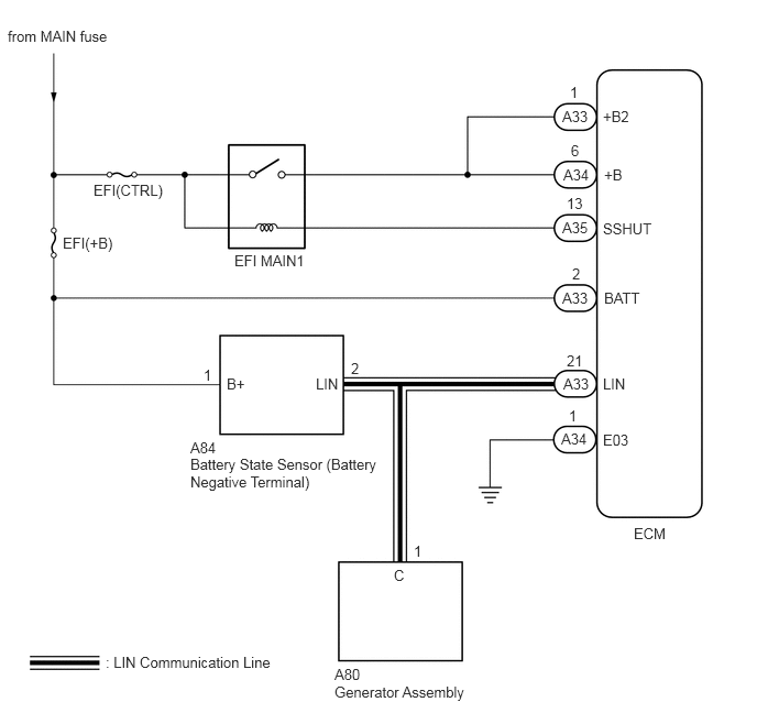
WIRING DIAGRAM
CAUTION / NOTICE / HINT
- NOTICE:
-
Inspect the fuses for circuits related to this system before performing the following inspection procedure.
PROCEDURE
Start the engine.
Idling with warm engine.
Measure the voltage according to the value(s) in the table below.
- Standard Voltage:
Tester Connection Condition Specified Condition Generator assembly positive (+) terminal - Body ground Always 10.8 V or more
OK
NG
Start the engine.
Measure the voltage according to the value(s) in the table below.
- Standard Voltage:
Tester Connection Condition Specified Condition Generator assembly positive (+) terminal - Body ground Engine Speed: 3000 rpm 10.8 V or more
OK
NG
Turn the ignition switch off.
Check the installation status of positive and negative battery terminals.
- OK:
There is no looseness at the connecting part of the terminals.
OK
NG
Starting the engine.
Measure the voltage according to the value(s) in the table below.
- Standard Voltage:
Tester Connection Condition Specified Condition A33-1 (+B2) - Body ground Idling 10.8 V or more A34-6 (+B) - Body ground Idling 10.8 V or more
OK
NG
Check for poor connection of connectors between the ECU, alternator, and the battery.
- OK:
There is no looseness at the connecting part of the connectors.
OK
NG
Connect the GTS to the DLC3.
Turn the ignition switch ON.
Turn the GTS on.
Clear the DTCs.
Click herePower Source / Network>FA20 (BATTERY / CHARGING)>CHARGING SYSTEM (for 150 A Type)>DTC CHECK / CLEAR
Turn the ignition switch off and wait at least 30 seconds.
Enter the following menus: Powertrain / Engine / Trouble Codes.
Check for DTCs.
Click herePower Source / Network>FA20 (BATTERY / CHARGING)>CHARGING SYSTEM (for 150 A Type)>DTC CHECK / CLEAR
| Result | Proceed to |
|---|---|
| DTC P0562 is output | A |
| DTC is not output | B |
OK
NG