K3-VE ENGINE CONTROL SFI SYSTEM P0011 Camshaft Position "A" - Timing Over-Advanced or System Performance (Bank 1) P0012 Camshaft Position "A" - Timing Over-Retarded (Bank 1)
DESCRIPTION
The Variable Valve Timing (VVT) system includes the ECM, Oil Control Valve (OCV) and VVT controller (camshaft timing sprocket assembly). The ECM sends a target duty-cycle control signal to the OCV. This control signal regulates the oil pressure supplied to the VVT controller. Camshaft timing control is performed according to engine operating conditions such as the intake air volume, throttle valve position and engine coolant temperature. The ECM controls the OCV based on the signals transmitted by several sensors. The VVT controller regulates the intake camshaft angle using oil pressure through the OCV. As a result, the relative positions of the camshaft and crankshaft are optimized, the engine torque and fuel economy improve, and the exhaust emissions decrease under overall driving conditions. The ECM detects the actual intake valve timing using signals from the camshaft and crankshaft position sensors, and performs feedback control. This is how the target intake valve timing is verified by the ECM.
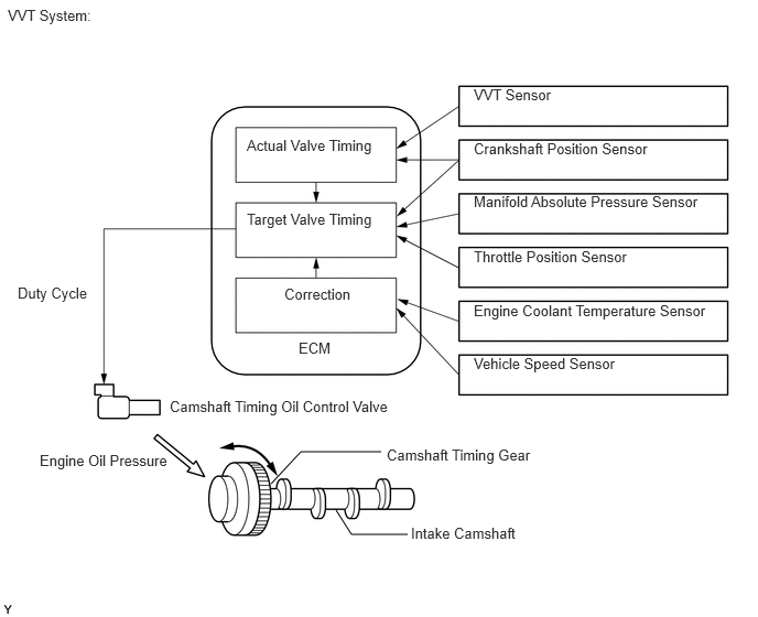
| DTC No. | Detection Item | DTC Detection Condition | Trouble Area | MIL | Memory |
|---|---|---|---|---|---|
| P0011 | Camshaft Position "A" - Timing Over-Advanced or System Performance (Bank 1) | Advanced camshaft timing Condition (a) or (b) continues after engine has warmed up and when engine speed 500 to 4000 rpm (2 trip detection logic) (a) Amount of valve timing change less than threshold (b) Current valve timing fixed |
·
Open or short in camshaft timing oil control valve assembly circuit ·
Valve timing ·
Camshaft timing oil control valve assembly ·
Camshaft timing oil control valve filter ·
Camshaft timing sprocket assembly ·
ECM |
Comes on | DTC stored |
| P0012 | Camshaft Position "A" - Timing Over-Retarded (Bank 1) | Retarded camshaft timing Condition (a) or (b) continues after engine has warmed up and when engine speed 500 to 4000 rpm (2 trip detection logic) (a) Amount of valve timing change less than threshold (b) Current valve timing fixed |
·
Open or short in camshaft timing oil control valve assembly circuit ·
Valve timing ·
Camshaft timing oil control valve assembly ·
Camshaft timing oil control valve filter ·
Camshaft timing sprocket assembly ·
ECM |
Comes on | DTC stored |
WIRING DIAGRAM
Refer to DTC P0010 (See page Engine / Hybrid System>K3-VE ENGINE CONTROL>SFI SYSTEM>P0010).
PROCEDURE
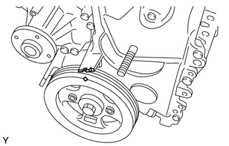
Turn the crankshaft clockwise, to align the timing mark of the crankshaft pulley with the indicator of the timing chain cover.
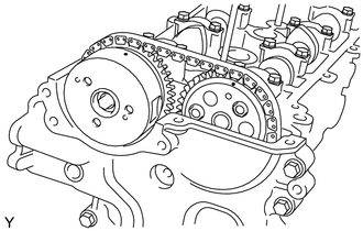
Check that the alignment marks of the camshaft timing sprocket are facing upward. If not, turn the crankshaft 1 revolution so they face upward.
Check for looseness or a jumped tooth of the timing chain.
- OK:
Alignment marks of the crankshaft pulley and camshaft pulley are aligned.
- Result:
Proceed to OK NG
OK
NG
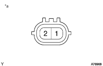
| *a | Component without harness connected
(Camshaft Timing Oil Control Valve Assembly) |
Start the engine.
Check the engine speed at check (1) and (2).
Check (1):
Disconnect the camshaft timing oil control valve assembly connector.
Check (2):
Apply battery voltage to the terminals of the camshaft timing oil control valve assembly.
- Result:
Check (1) Check (2) Proceed To Normal engine speed Rough idle or engine stall A Condition other than above B
Reconnect the camshaft timing oil control valve assembly connector.
A
B
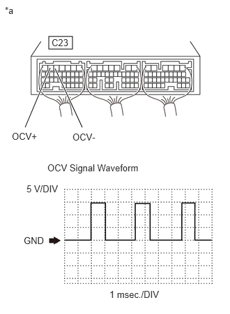
| *a | Component with harness connected
(ECM) |
Inspect using an oscilloscope.
During idling, check the waveform between the terminals of the ECM connector.
| Terminal No. (Symbol) | Tool Setting | Condition |
|---|---|---|
| C23-6 (OCV+) - C23-5 (OCV-) | 5 V/DIV, 1 msec./DIV | Idling |
- OK:
The waveform exists accordance with the engine speed (Refer to the waveform in the illustration).
- HINT:
- ·
The waveforms shown in the illustration are at engine idling speed.
·The oscilloscope waveform shown as an example does not include noise or chattering waveforms.
·The waveform amplitudes differ slightly depending on the vehicle conditions.
- Result:
Result Proceed to OK A NG (for LHD) B NG (for RHD) C
A
B
C
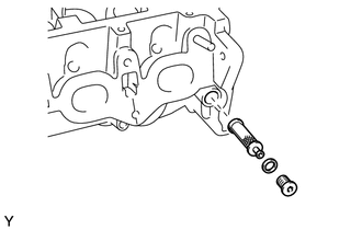
Remove the OCV (Camshaft Timing Oil Control Valve) filter.
Check that the filter is not clogged.
- OK:
Filter is not clogged.
Reinstall the OCV filter.
- Result:
Proceed to OK NG
OK
NG
OK
NG
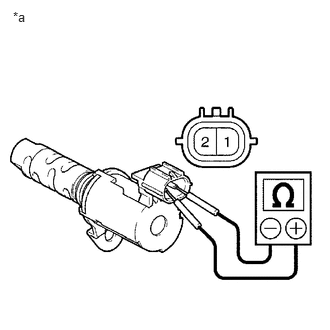
| *a | Component without harness connected
(Camshaft Timing Oil Control Valve Assembly) |
Remove the camshaft timing oil control valve assembly.
Measure the resistance according to the value(s) in the table below.
- Standard Resistance:
Tester Connections Condition Specified Conditions 1 - 2 20°C (68°F) 6.9 to 7.9 Ω
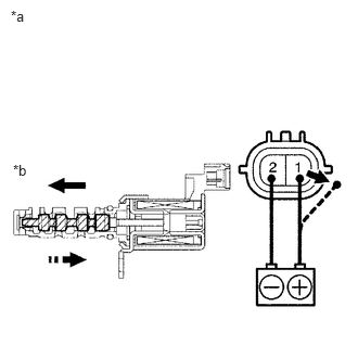
| *a | Component without harness connected
(Camshaft Timing Oil Control Valve Assembly) |
| *b | Valve Moves |
Connect the positive battery terminal to terminal 1 and connect the negative battery terminal to terminal 2. Check the valve operation.
- OK:
Valve moves quickly.
Reinstall the camshaft timing oil control valve assembly.
- Result:
Proceed to OK NG
OK
NG
Inspect the camshaft timing sprocket assembly.
Click hereEngine / Hybrid System>K3-VE ENGINE MECHANICAL>ENGINE UNIT>INSPECTION
- Result:
Proceed to OK NG
OK
NG
- OK:
No blockage.
- Result:
Result Proceed to NG A OK (for LHD) B OK (for RHD) C
A
B
C