K3-VE ENGINE CONTROL SFI SYSTEM P0535 A/C Evaporator Temperature Sensor Circuit
DESCRIPTION
The No. 1 cooler thermistor (A/C evaporator temperature sensor) is used to control the operation of the compressor. The No. 1 cooler thermistor has a thermistor that detects the surface temperature of the evaporator. If the temperature is below approximately 3°C (37.4 °F), the ECM turns the compressor OFF. This control is to protect the evaporator by preventing frost from forming on it.
| DTC No. | Detection Item | DTC Detection Condition | Trouble Area | MIL | Memory |
|---|---|---|---|---|---|
| P0535 | A/C Evaporator Temperature Sensor Circuit | Voltage output of thermistor below 0.1 V or above 4.85 V for more than 0.5 seconds while air conditioner operated
(1 trip detection logic) |
·
Open or short in No. 1 cooler thermistor circuit ·
No. 1 cooler thermistor ·
ECM |
- | DTC stored |
WIRING DIAGRAM
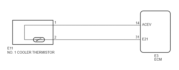
CAUTION / NOTICE / HINT
- HINT:
-
Read freeze frame data using an intelligent tester. Freeze frame data record the engine condition when malfunctions are detected. When troubleshooting, freeze frame data can help determine if the vehicle was moving or stationary, if the engine was warmed up or not, if the air-fuel ratio was lean or rich, and other data, from the time the malfunction occurred.
PROCEDURE
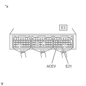
| *a | Rear view of wire harness connector
(to ECM) |
Turn the ignition switch to ON.
Turn the cooler control switch on.
Measure the voltage according to the value(s) in the table below.
- Standard Voltage:
Tester Connection Switch Condition Specified Condition E3-14 (ACEV) - E3-31 (E21) Ignition switch ON 0.15 to 4.8 V
- Result:
Result Proceed to NG A OK (for LHD) B OK (for RHD) C
A
B
C
Disconnect the No. 1 cooler thermistor connector.
Disconnect the ECM connector.
Measure the resistance according to the value(s) in the table below.
- Standard Resistance (Check for Open):
Tester Connection Condition Specified Condition E11-1 - E3-14 (ACEV) Always Below 1 Ω E11-2 - E3-31 (E21) Always Below 1 Ω
- Standard Resistance (Check for Short):
Tester Connection Condition Specified Condition E11-1 or E3-14 (ACEV) - Body ground Always 10 kΩ or higher
Reconnect the No. 1 cooler thermistor connector.
Reconnect the ECM connector.
- Result:
Proceed to OK NG
OK
NG
Inspect the No. 1 cooler thermistor.
Click hereVehicle Interior>HEATING / AIR CONDITIONING>FRONT EVAPORATOR TEMPERATURE SENSOR>INSPECTION
- Result:
Result Proceed to NG A OK (for LHD) B OK (for RHD) C
A
B
C