Home › Engine / Hybrid System › 3SZ-VE ENGINE CONTROL › SFI SYSTEM(w/o Rear Heated Oxygen Sensor) › 2011.11–2015.08
RM19Y0E _51 Engine / Hybrid System _002968 3SZ-VE ENGINE CONTROL _0014987 SFI SYSTEM(w/o Rear Heated Oxygen Sensor) J

3SZ-VE ENGINE CONTROL  SFI SYSTEM(w/o Rear Heated Oxygen Sensor)  Fuel Pump Control Circuit  


DESCRIPTION

When the engine is cranked, a current flows from terminal ST of the ignition switch to terminal STA of the ECM (STA signal).

When signals STA, N and N2 are input to the ECM, transistor (Tr) turns ON, a current flows to the coil of the F/P (fuel pump) relay, the relay switch turns ON, and a current flows to the fuel pump. The fuel pump is then actuated.

While the N and N2 signals are generated (engine running), the ECM keeps Tr ON (fuel pump relay ON) and the fuel pump also keeps operating.
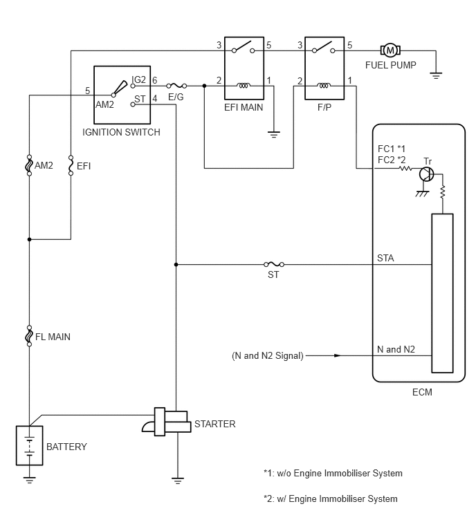
A263582E06
0.698,6.646 1.542,6.948 0.844,0.302 10 BATTERY 2.927,6.302 3.75,6.615 0.823,0.313 10 STARTER 0.531,4.99 1.229,5.292 0.698,0.302 10 FL MAIN 0.521,2.406 1.021,2.771 0.5,0.365 10 AM2 1.156,2.417 1.646,2.729 0.49,0.313 10 EFI 1.438,1.49 1.823,1.771 0.385,0.281 10 AM2 1.979,1.115 2.417,1.427 0.438,0.313 10 IG2 2.021,1.406 2.427,1.688 0.406,0.281 10 ST 2.531,1.375 3.031,1.729 0.5,0.354 10 E/G 1.24,1.906 2.635,2.313 1.396,0.406 10 IGNITION SWITCH 3.375,1.531 4.177,1.802 0.802,0.271 10 EFI MAIN 4.781,1.531 5.271,1.948 0.49,0.417 10 F/P 5.5,0.896 6.448,1.198 0.948,0.302 10 FUEL PUMP 6.208,5.823 6.76,6.156 0.552,0.333 10 ECM 5.688,2.156 6.24,2.427 0.552,0.271 10 FC1 *1 5.677,3.802 6.208,4.156 0.531,0.354 10 STA 4.031,4.052 4.573,4.344 0.542,0.292 10 ST 5.677,5.177 6.458,5.479 0.781,0.302 10 N and N2 3.49,5.271 4.708,5.656 1.219,0.385 10 (N and N2 Signal) 6.375,2.344 6.667,2.635 0.292,0.292 10 Tr 5.229,0.594 5.542,0.896 0.313,0.302 10 5 5.229,1.125 5.49,1.458 0.26,0.333 10 1 4.479,0.594 4.76,0.917 0.281,0.323 10 3 4.479,1.135 4.781,1.417 0.302,0.281 10 2 4.01,0.594 4.344,0.885 0.333,0.292 10 5 4.01,1.125 4.313,1.417 0.302,0.292 10 1 3.26,0.594 3.583,0.948 0.323,0.354 10 3 3.26,1.125 3.521,1.406 0.26,0.281 10 2 2.292,1.125 2.604,1.406 0.313,0.281 10 6 2.292,1.396 2.667,1.719 0.375,0.323 10 4 1.281,1.281 1.573,1.615 0.292,0.333 10 5 5.688,2.323 6.26,2.563 0.573,0.24 10 FC2 *2 3.969,7.042 7.125,7.292 3.156,0.25 10 *1: w/o Engine Immobiliser System 3.969,7.427 7.125,7.677 3.156,0.25 10 *2: w/ Engine Immobiliser System

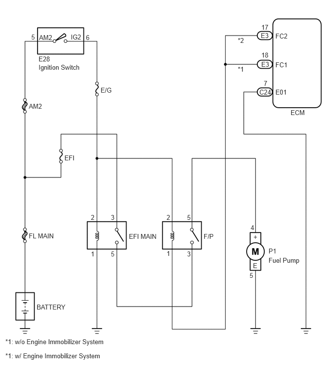
WIRING DIAGRAM

A268113E02
0.781,6.479 1.719,6.875 0.938,0.396 10 BATTERY 0.615,4.958 1.313,5.302 0.698,0.344 10 FL MAIN 1.375,3.292 1.802,3.656 0.427,0.365 10 EFI 0.615,2.188 1.104,2.479 0.49,0.292 10 AM2 0.833,0.719 1.354,1.073 0.521,0.354 10 AM2 1.51,0.708 2.021,1.094 0.51,0.385 10 IG2 0.823,1.177 1.219,1.448 0.396,0.271 10 E28 0.823,1.354 1.854,1.698 1.031,0.344 10 Ignition Switch 2.146,1.844 2.635,2.271 0.49,0.427 10 E/G 2.75,4.969 3.552,5.24 0.802,0.271 10 EFI MAIN 5.729,5.479 6.531,5.885 0.802,0.406 10 Fuel Pump 5.875,1.885 6.302,2.219 0.427,0.333 10 E01 5.531,1.885 5.99,2.198 0.458,0.313 10 C24 5.625,1.698 5.885,1.979 0.26,0.281 10 7 5.875,1.302 6.333,1.583 0.458,0.281 10 FC1 5.573,1.292 6.01,1.656 0.438,0.365 10 E3 5.573,1.094 5.906,1.26 0.333,0.167 10 18 6.198,2.323 6.719,2.698 0.521,0.375 10 ECM 0.667,0.708 0.917,0.969 0.25,0.26 10 5 1.833,0.719 2.135,1.01 0.302,0.292 10 6 1.938,4.563 2.281,4.906 0.344,0.344 10 2 1.938,5.344 2.229,5.646 0.292,0.302 10 1 2.365,4.563 2.708,4.865 0.344,0.302 10 3 2.365,5.344 2.594,5.635 0.229,0.292 10 5 3.552,4.563 3.792,4.823 0.24,0.26 10 2 3.552,5.333 3.865,5.635 0.313,0.302 10 1 3.99,4.563 4.271,4.813 0.281,0.25 10 5 3.99,5.344 4.25,5.635 0.26,0.292 10 3 4.344,4.969 4.729,5.25 0.385,0.281 10 F/P 5.344,4.781 5.656,4.99 0.313,0.208 10 4 5.729,5.281 6.177,5.531 0.448,0.25 10 P1 5.323,5.802 5.708,6.094 0.385,0.292 10 5 5.406,4.979 5.719,5.198 0.313,0.219 10 + 5.396,5.594 5.771,5.833 0.375,0.24 10 E 5.875,0.688 6.375,0.979 0.5,0.292 10 FC2 5.563,0.677 5.938,0.979 0.375,0.302 10 E3 5.573,0.5 5.958,0.781 0.385,0.281 10 17 5.073,1.396 5.479,1.688 0.406,0.292 10 *1 5.073,0.781 5.375,1.021 0.302,0.24 10 *2 0.115,7.219 2.771,7.427 2.656,0.208 10 *1: w/o Engine Immobilizer System 0.115,7.521 2.771,7.729 2.656,0.208 10 *1: w/ Engine Immobilizer System

PROCEDURE

1.CHECK OPERATION OF FUEL PUMP
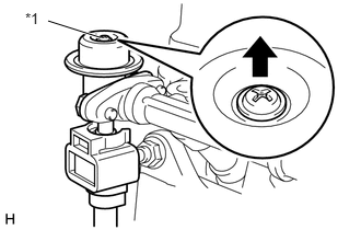
a.
A261189C01
0.948,0.354 0.458,0.198 true 0.24,0.094 0.698,0.5 0.458,0.406 10 *1
*1 Screw


Start the engine (engine cranking operation).


b.

Check that the fuel pulsation damper extrudes its screw.

Standard:

Fuel pulsation damper extrudes its screw.


HINT:
·

After the engine starts, check that the fuel pump operating sound occurs.

·

The fuel pump can be operated the engine running.

Click hereEngine / Hybrid System>3SZ-VE FUEL>FUEL SYSTEM>ON-VEHICLE INSPECTION


Result:
Proceed to
OK
NG


OK

PROCEED TO NEXT CIRCUIT INSPECTION SHOWN ON PROBLEM SYMPTOMS TABLE

NG

2.INSPECT ECM (+B1 VOLTAGE)

OK

3.INSPECT FUEL PUMP RELAY (F/P RELAY)

NG

3.INSPECT FUEL PUMP RELAY (F/P RELAY)
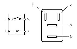
a.
A167865N12
2.01,0.594 1.552,0.24 true 2.656,0.625 3.063,0.25 true 2.531,1.125 3.063,1.125 true 2.531,1.625 3.073,1.625 true 1.208,0.76 1.542,1.083 0.333,0.323 10 5 0.208,0.771 0.615,1.198 0.406,0.427 10 3 1.229,1.313 1.594,1.708 0.365,0.396 10 2 0.208,1.292 0.563,1.594 0.354,0.302 10 1 1.417,0.125 1.792,0.458 0.375,0.333 10 1 3.125,0.135 3.427,0.438 0.302,0.302 10 2 3.125,1.552 3.427,1.823 0.302,0.271 10 3 3.125,1.042 3.427,1.333 0.302,0.292 10 5

Remove the F/P relay from the fuse block.


b.

Measure the resistance according to the value(s) in the table below.

Standard Resistance:
Tester Connection Condition Specified Condition
3 - 5 No battery voltage applied to terminals 1 and 2 10 kΩ or higher
3 - 5 Battery voltage applied to terminals 1 and 2 Below 1 Ω


c.

Reinstall the F/P relay.

Result:
Proceed to
OK
NG


OK

4.INSPECT ECM (FC VOLTAGE)

NG

REPLACE FUEL PUMP RELAY

4.INSPECT ECM (FC VOLTAGE)
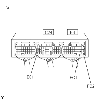
a.
A141531C21
1.479,1.01 1.844,1.198 0.365,0.188 2.313,1.01 2.677,1.198 0.365,0.188 1.063,2.542 1.365,1.563 true 3.115,2.844 2.844,1.75 true 2.573,2.542 2.771,1.74 true 0.917,2.563 1.396,2.875 0.479,0.313 10 E01 2.99,2.875 3.375,3.104 0.385,0.229 10 FC2 0.188,0.167 0.688,0.677 0.5,0.51 10 *a 1.542,1.031 2.073,1.5 0.531,0.469 10 C24 2.406,1.031 2.813,1.458 0.406,0.427 10 E3 2.396,2.583 2.823,2.875 0.427,0.292 10 FC1
*a Component with harness connected
(ECM)


Turn the ignition switch to ON.


b.

Measure the voltage according to the value(s) in the table below.

Standard Voltage (w/o Engine Immobilizer System):
Tester Connections Switch Condition Specified Conditions
E3-18 (FC1) - C24-7 (E01) Ignition switch ON 11 to 14 V


Standard Voltage (w/ Engine Immobilizer System):
Tester Connections Switch Condition Specified Conditions
E3-17 (FC2) - C24-7 (E01) Ignition switch ON 11 to 14 V


HINT:

The fuel pump operates for 2 seconds after the ignition switch has been turned to ON. If the ignition switch was turned to ON with EFIT and E terminals of DLC3 connected, the fuel pump operates for 8 seconds. The voltage between FC and E01 decreases to below 2V in both cases.


Result:
Proceed to
OK
NG


OK

5.INSPECT FUEL PUMP

NG

9.CHECK HARNESS AND CONNECTOR (ECM - F/P RELAY)
5.INSPECT FUEL PUMP
a.

Inspect the fuel pump.

Click hereEngine / Hybrid System>3SZ-VE FUEL>FUEL PUMP>INSPECTION

Result:
Proceed to
OK
NG


OK

6.CHECK HARNESS AND CONNECTOR (F/P RELAY - FUEL PUMP)

NG

6.CHECK HARNESS AND CONNECTOR (F/P RELAY - FUEL PUMP)
a.

Remove the F/P relay from the fuse block.


b.

Disconnect the fuel pump connector.


c.

Measure the resistance according to the value(s) in the table below.

Standard Resistance (Check for Open):
Tester Connections Condition Specified Conditions
F/P relay (5) - P1-4 (+) Always Below 1 Ω


Standard Resistance (Check for Short):
Tester Connections Condition Specified Conditions
F/P relay (5) or P1-4 (+) - Body ground Always 10 kΩ or higher


d.

Reconnect the fuel pump connector.


e.

Reinstall the F/P relay.

Result:
Proceed to
OK
NG


OK

7.CHECK HARNESS AND CONNECTOR (FUEL PUMP - BODY GROUND)

NG

REPAIR OR REPLACE HARNESS OR CONNECTOR

7.CHECK HARNESS AND CONNECTOR (FUEL PUMP - BODY GROUND)
a.

Disconnect the fuel pump connector.


b.

Measure the resistance according to the value(s) in the table below.

Standard Resistance (Check for Open):
Tester Connections Condition Specified Conditions
P1-5 (E) - Body ground Always Below 1 Ω


c.

Reconnect the fuel pump connector.

Result:
Proceed to
OK
NG


OK

8.CHECK HARNESS AND CONNECTOR (F/P RELAY - EFI MAIN RELAY)

NG

REPAIR OR REPLACE HARNESS OR CONNECTOR

8.CHECK HARNESS AND CONNECTOR (F/P RELAY - EFI MAIN RELAY)
a.

Remove the F/P relay from the fuse block.


b.

Remove the EFI MAIN relay from the fuse block.


c.

Measure the resistance according to the value(s) in the table below.

Standard Resistance (Check for Open):
Tester Connections Condition Specified Conditions
F/P relay (3) - EFI MAIN relay (5) Always Below 1 Ω


Standard Resistance (Check for Short):
Tester Connections Condition Specified Conditions
F/P relay (3) or EFI MAIN relay (5) - Body ground Always 10 kΩ or higher


d.

Reinstall the EFI MAIN relay.


e.

Reinstall the F/P relay.

Result:
Result Proceed to
NG A
OK (for LHD) B
OK (for RHD) C


A

REPAIR OR REPLACE HARNESS OR CONNECTOR

B

C

9.CHECK HARNESS AND CONNECTOR (ECM - F/P RELAY)
a.

Disconnect the ECM connector.


b.

Remove the F/P relay from the fuse block.


c.

Measure the resistance according to the value(s) in the table below.

Standard Resistance (Check for Open) (w/o Engine Immobilizer System):
Tester Connections Condition Specified Conditions
E3-18 (FC1) - F/P relay (1) Always Below 1 Ω


Standard Resistance (Check for Open) (w/ Engine Immobilizer System):
Tester Connections Condition Specified Conditions
E3-17 (FC2) - F/P relay (1) Always Below 1 Ω


Standard Resistance (Check for Short) (w/o Engine Immobilizer System):
Tester Connections Condition Specified Conditions
E3-18 (FC1) or F/P relay (1) - Body ground Always 10 kΩ or higher


Standard Resistance (Check for Short) (w/ Engine Immobilizer System):
Tester Connections Condition Specified Conditions
E3-17 (FC2) or F/P relay (1) - Body ground Always 10 kΩ or higher


d.

Reconnect the ECM connector


e.

Reinstall the F/P relay.

Result:
Proceed to
OK
NG


OK

REPAIR OR REPLACE HARNESS OR CONNECTOR (IGNITION SWITCH - F/P RELAY)

NG

REPAIR OR REPLACE HARNESS OR CONNECTOR