3SZ-VE ENGINE CONTROL SFI SYSTEM(w/ Rear Heated Oxygen Sensor) P0500 Vehicle Speed Sensor "A"
DESCRIPTION
Manual transmission w/o multi information display models:
Based on speed signals, a microcomputer in the combination meter calculates the vehicle speed and inputs the signals to the ECM. The ECM also determines the vehicle speed based on these signals.
Manual transmission w/ multi information display models:
The ECM directly receives vehicle speed signal from the combination meter assembly through the CAN communication lines.
Automatic transmission models:
The ECM directly receives vehicle speed signal from the TCM through the CAN communication lines.
| DTC No. | Detection Item | DTC Detection Condition | Trouble Area | MIL | Memory |
|---|---|---|---|---|---|
| P0500 | Vehicle Speed Sensor "A" | During deceleration, speed signal from combination meter not input to ECM for more than 3 seconds even though engine speed 500 to 4000 rpm under fuel-cut control
(1 trip detection logic) |
·
Open or short in speed signal circuit ·
Speedometer circuit ·
ECM |
Comes on | DTC stored |
WIRING DIAGRAM
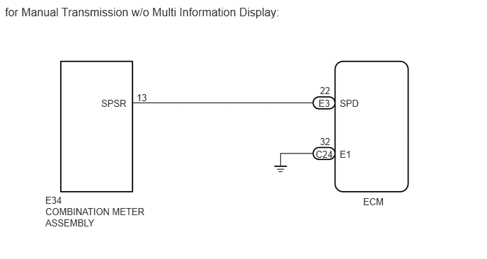
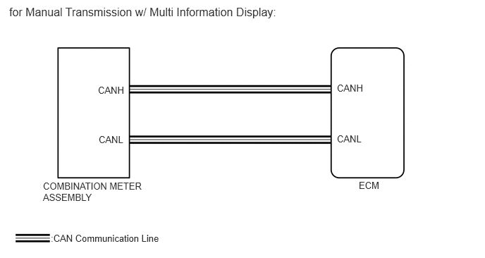
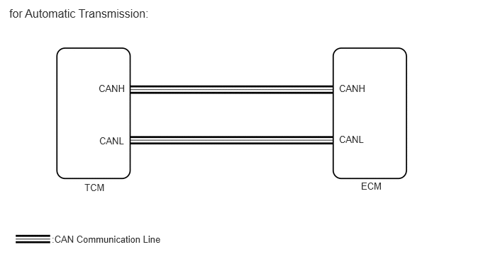
CAUTION / NOTICE / HINT
- HINT:
-
Read freeze frame data using the intelligent tester or Techstream. Freeze frame data record the engine condition when malfunctions are detected. When troubleshooting, freeze frame data can help determine if the vehicle was moving or stationary, if the engine was warmed up or not, if the air-fuel ratio was lean or rich, and other data, from the time the malfunction occurred.
PROCEDURE
Check transmission type.
- Result:
Transmission type Proceed to Manual transmission A Automatic transmission B
A
B
Connect the intelligent tester or Techstream to the DLC3.
Turn the ignition switch to ON.
Turn the intelligent tester or Techstream on.
Enter the following menus: Powertrain / Engine / Trouble Codes.
- Powertrain > Engine > Trouble Codes
- 50001 206
Read DTCs.
- Result:
Result Proceed to P0500 and other DTCs A P0500 B
- HINT:
-
If any DTCs other than P0500, which related to the CAN communication or the ABS system, are output, troubleshoot those DTCs first.
A
B
Connect the intelligent tester or Techstream to the DLC3.
Turn the ignition switch to ON.
Turn the intelligent tester or Techstream on.
Enter the following menus: Powertrain / Engine / Trouble Codes.
- Powertrain > Engine > Trouble Codes
- 50001 206
Read DTCs.
- Result:
Result Proceed to P0500 A P0500 and other DTCs B
- HINT:
-
If any DTCs other than P0500, which related to the CAN communication or the automatic transmission system, are output, troubleshoot those DTCs first.
A
B
Drive the vehicle and check whether the operation of the speedometer in the combination meter is normal.
- OK:
Speedometer operation is normal.
- Result:
Vehicle type Result Result Manual transmission w/o multi information display models OK A NG B Manual transmission w/ multi information display models OK (for LHD) C OK (for RHD) D NG B Automatic transmission models OK (for LHD) C OK (for RHD) D NG E
A
B
C
D
E
Shift the transmission gear to the neutral position.
Jack up one of the rear wheels.
Turn the ignition switch to ON.
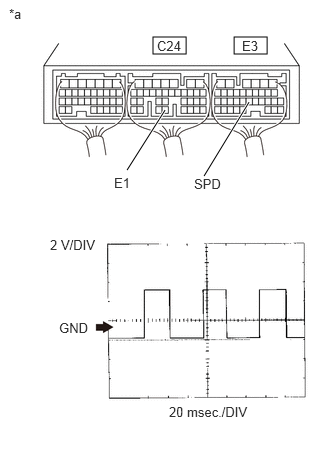
| *a | Component with harness connected
(ECM) |
Turn the rear wheel slowly, and measure the voltage of the ECM connectors.
- Standard Voltage:
Tester Connections Switch Condition Specified Condition E3-22 (SPD) - C24-32 (E1) Ignition switch ON Voltage generated intermittently
(Pulse signal generated)
- HINT:
-
Inspect SPD signal using an oscilloscope. Check the waveform between the terminals of the ECM connectors, maintaining a vehicle speed of 20 km/h (12 mph).
Terminal No. (Symbol) Tool Setting Condition E3-22 (SPD) - C24-32 (E1) 2 V/DIV, 20 msec./DIV Vehicle speed 20 km/h (12 mph)
- Result:
Condition Proceed to Voltage not generated intermittently
(Output voltage fixed)A Voltage generated intermittently
(Pulse signal generated)
(for LHD)B Voltage generated intermittently
(Pulse signal generated)
(for RHD)C
A
B
C
Disconnect the combination meter assembly connector.
Disconnect the ECM connector.
Measure the resistance according to the value(s) in the table below.
- Standard Resistance (Check for Open):
Tester Connection Condition Specified Condition E34-13 (SPSR) - E3-22 (SPD) Always Below 1 Ω
- Standard Resistance (Check for Short):
Tester Connection Condition Specified Condition E34-13 (SPSR) or E3-22 (SPD) - Body ground Always 10 kΩ or higher
Reconnect the combination meter assembly connector.
Reconnect the ECM connector.
- Result:
Proceed to OK NG
OK
NG