A4Q AUTOMATIC TRANSMISSION / TRANSAXLE AUTOMATIC TRANSMISSION SYSTEM Shift Solenoid Malfunction
DESCRIPTION
| Item | Function |
|---|---|
| Shift solenoid valve SL1 | Control the B1 brake hydraulic pressure |
| Shift solenoid valve SL2 | Control the C2 brake hydraulic pressure |
| Shift solenoid valve SL3 | Control the line pressure that controls the hydraulic pressure for the C3 clutch and that for the B2 brake |
| Shift solenoid valve SL | Switch the lock-up relay valve |
| Shift solenoid valve DSU | Control the lock-up clutch hydraulic pressure |
| Shift solenoid valve SR | Switch the solenoid relay valve |
- HINT:
- ·
Start the inspection from step 1 when shift solenoid valve SL1 malfunctions.
·Start the inspection from step 2 when shift solenoid valve SL2 malfunctions.
·Start the inspection from step 3 when shift solenoid valve SL3 malfunctions.
·Start the inspection from step 4 when shift solenoid valve SL malfunctions.
·Start the inspection from step 5 when shift solenoid valve DSU malfunctions.
·Start the inspection from step 6 when shift solenoid valve SR malfunctions.
PROCEDURE
Check and find which solenoid valve is malfunctioning.
- Result:
Result proceed to Shift solenoid valve SL1 malfunctions. A Shift solenoid valve SL2 malfunctions. B Shift solenoid valve SL3 malfunctions. C Shift solenoid valve SL malfunctions. D Shift solenoid valve DSU malfunctions. E Shift solenoid valve SR malfunctions. F
A
B
C
D
E
F
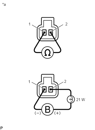
| *a | Component without harness connected
(Shift Solenoid Valve SL1) |
Remove the shift solenoid valve SL1.
Measure the resistance according to the value(s) in the table below.
- Standard resistance:
Tester Connection Condition Specified Condition 1 - 2 20°C (68°F) 5.0 to 5.6 Ω
Connect the positive (+) lead with a 21 W bulb to terminal 2 and the negative (-) lead to terminal 1 of the solenoid valve connector, then check the movement of the valve.
- NOTICE:
- ·
Never directly apply battery voltage to the solenoid valve connector (Do not allow a current of 1 A or more to flow). Perform the operation check via the specified bulb (resistance).
·If a current of 1 A or more flows, the characteristic of the solenoid valve changes.
- OK:
The solenoid valve makes an operating sound.
- Result:
proceed to OK NG
OK
NG
- OK:
There are no foreign objects on each valve and they operate smoothly.
- Result:
proceed to OK NG
OK
NG
Refer to the TORQUE CONVERTER AND DRIVE PLATE.
Click hereDrivetrain>A4Q AUTOMATIC TRANSMISSION / TRANSAXLE>TORQUE CONVERTER AND DRIVE PLATE>INSPECTION
- OK:
The torque converter assembly operates normally.
- Result:
proceed to OK NG
OK
NG
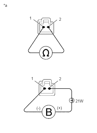
| *a | Component without harness connected
(Shift Solenoid Valve SL2) |
Remove the shift solenoid valve SL2.
Measure the resistance according to the value(s) in the table below.
- Standard resistance:
Tester Connection Condition Specified Condition 1 - 2 20°C (68°F) 5.1 to 5.5 Ω
Connect the positive (+) lead with a 21 W bulb to terminal 2 and the negative (-) lead to terminal 1 of the solenoid valve connector, then check the movement of the valve.
- NOTICE:
- ·
Never directly apply battery voltage to the solenoid valve connector (Do not allow a current of 1 A or more to flow). Perform the operation check via the specified bulb (resistance).
·If a current of 1 A or more flows, the characteristic of the solenoid valve changes.
- OK:
The solenoid valve makes an operating sound.
- Result:
proceed to OK NG
OK
NG
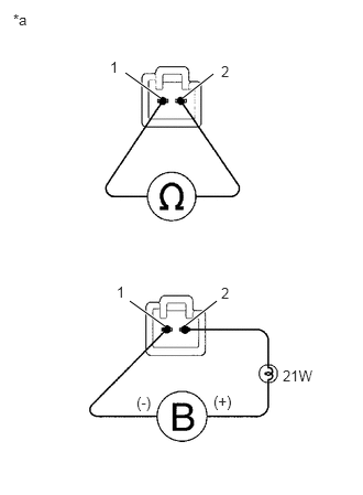
| *a | Component without harness connected
(Shift Solenoid Valve SL3) |
Remove the shift solenoid valve SL3.
Measure the resistance according to the value(s) in the table below.
- Standard resistance:
Tester Connection Condition Specified Condition 1 - 2 20°C (68°F) 5.1 to 5.5 Ω
Connect the positive (+) lead with a 21 W bulb to terminal 2 and the negative (-) lead to terminal 1 of the solenoid valve connector, then check the movement of the valve.
- NOTICE:
- ·
Never directly apply battery voltage to the solenoid valve connector (Do not allow a current of 1 A or more to flow). Perform the operation check via the specified bulb (resistance).
·If a current of 1 A or more flows, the characteristic of the solenoid valve changes.
- OK:
The solenoid valve makes an operating sound.
- Result:
proceed to OK NG
OK
NG
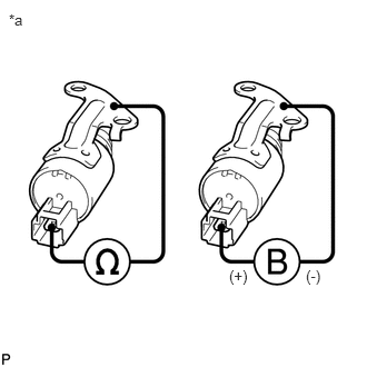
| *a | Component without harness connected
(Shift Solenoid Valve SL) |
Remove the shift solenoid valve SL.
Measure the resistance according to the value(s) in the table below.
- Standard resistance:
Tester Connection Condition Specified Condition Solenoid Connector (SL) - Solenoid Body (SL) 20°C (68°F) 14 to 18 Ω
Connect the positive (+) lead to the terminal of the solenoid valve connector, and the negative (-) lead to the solenoid valve body.
- OK:
The solenoid valve makes an operating sound.
- Result:
proceed to OK NG
OK
NG
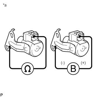
| *a | Component without harness connected
(Shift Solenoid Valve DSU) |
Remove the shift solenoid valve DSU.
Measure the resistance according to the value(s) in the table below.
- Standard resistance:
Tester Connection Condition Specified Condition Solenoid Connector (DSU) - Solenoid Body (DSU) 20°C (68°F) 11 to 13 Ω
Connect the positive (+) lead to the terminal of the solenoid valve connector, and the negative (-) lead to the solenoid valve body.
- OK:
The solenoid valve makes an operating sound.
- Result:
proceed to OK NG
OK
NG
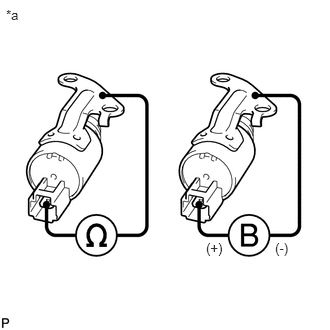
| *a | Component without harness connected
(Shift Solenoid Valve SR) |
Remove the shift solenoid valve SR.
Measure the resistance according to the value(s) in the table below.
- Standard resistance:
Tester Connection Condition Specified Condition Solenoid Connector (SR) - Solenoid Body (SR) 20°C (68°F) 14 to 18 Ω
Connect the positive (+) lead to the terminal of the solenoid valve connector, and the negative (-) lead to the solenoid valve body.
- OK:
The solenoid valve makes an operating sound.
- Result:
proceed to OK NG
OK
NG