POWER ASSIST SYSTEMS POWER STEERING SYSTEM C1541/41 Speed Sensor Malfunction C1571/71 Speed Sensor Malfunction (Test Mode DTC)
DESCRIPTION
Based on the vehicle speed signal received from the combination meter assembly, the power steering ECU assembly adjusts the amount of power assist according to the vehicle speed. The power steering ECU assembly monitors the speed signal input and stores a DTC if a malfunction is detected. While a malfunction exists in the vehicle speed signal, fail-safe operation maintains the amount of power assist at the level used for a speed of 100 km/h (62 mph).
- NOTICE:
-
Revving the engine while the vehicle is stopped may cause DTC C1541 to be stored.
- HINT:
- ·
If C1541 is stored while the vehicle is stopped, driving the vehicle for 5 minutes or more and then turning the ignition switch off will clear the DTC.
·A voltage of 12 V or 5 V is output from each ECU and then input to the combination meter. Each ECU controls its respective system based on the vehicle speed pulse signal.
·If a short occurs in any of the ECUs or in a wire harness connected to an ECU, all systems in the diagram below will not operate normally.
| DTC No. | Detection Item | Trouble Area | Warning Indicate | Return-to-normal Condition |
|---|---|---|---|---|
| C1541/41 | Speed Sensor Malfunction | ·
Vehicle speed signal circuit ·
Combination meter assembly ·
Power steering ECU assembly |
Comes on | Ignition switch ON again |
| C1571/71 | Speed Sensor Malfunction (Test Mode DTC) | ·
Vehicle speed signal circuit ·
Combination meter assembly ·
Power steering ECU assembly |
Comes on | - |
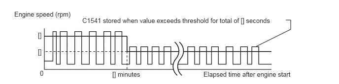
Speed Sensor Malfunction: An engine speed of [] rpm or more is detected [] minutes or more after the engine is started.
WIRING DIAGRAM
PROCEDURE
Perform the signal check in the Test Mode procedure.
Click hereSteering>POWER ASSIST SYSTEMS>POWER STEERING SYSTEM>TEST MODE PROCEDURE
- OK:
Test mode DTC C1571 is cleared.
- Result:
Proceed to OK NG
OK
Click hereGeneral>INTRODUCTION>HOW TO TROUBLESHOOT ECU CONTROLLED SYSTEMS>HOW TO PROCEED WITH TROUBLESHOOTING
NG
The circuits that send vehicle speed signals to this system are inspected in the meter system.
Click hereVehicle Interior>METER / GAUGE / DISPLAY>METER / GAUGE SYSTEM>Speedometer Malfunction
During inspection for the meter section, if there is an instruction that indicates to go back to inspections for each system, proceed to the next step.
- Result:
Proceed to NEXT
NEXT
Disconnect the E34 combination meter assembly connector.
Click hereSteering>POWER ASSIST SYSTEMS>POWER STEERING SYSTEM>TEST MODE PROCEDURE
Disconnect the E27 power steering ECU assembly connector.
Measure the resistance according to the value(s) in the table below.
- Standard Resistance:
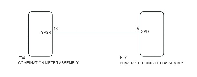
Tester Connection Switch Condition Specified Condition E27-5 (SPD) - E34-13 (SPSR) Always Below 1 Ω E27-5 (SPD) - Body ground Always 10 kΩ or higher
- Result:
Proceed to OK NG
OK
NG
Reconnect the E27 power steering ECU assembly connector.
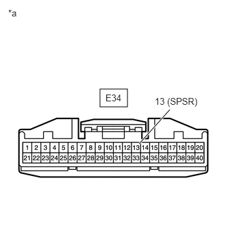
| *a | Front view of wire harness connector
(to Combination meter) |
Measure the voltage according to the value(s) in the table below.
- Standard Voltage:
Tester Connection Switch Condition Specified Condition E34-13 (SPSR) - Body ground Ignition switch ON 11 to 14 V
- Result:
Proceed to OK NG
OK
NG
Reconnect the E34 combination meter assembly connector.
Use a lift to raise the vehicle until the tires are off the ground.
Start the engine.
Depress the clutch pedal.
Move the shift lever to the 1st position.
Engage the clutch.
Check that the front wheels rotate slowly.
- CAUTION:
-
Be careful not to get caught in the front wheels while they are rotating.
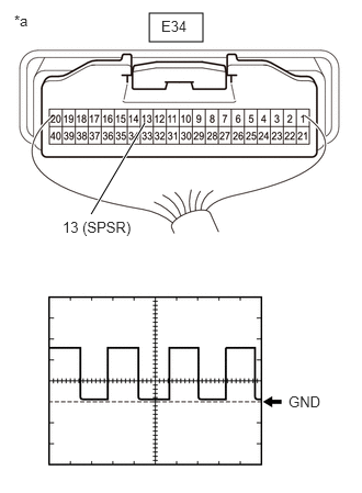
| *a | Component with harness connected
(Combination meter assembly) |
Check the signal waveform according to the condition(s) in the table below.
- Standard Voltage:
Tester Connection Switch Condition Specified Condition E34-13 (SPSR) - Body ground Front wheels rotating at speed corresponding to vehicle speed of approximately 20 km/h (12 mph) Correct waveform is as shown
| Item | Condition |
|---|---|
| Tool setting | 5 V/DIV ., 10 ms/DIV . |
- HINT:
-
The wavelength becomes shorter as the vehicle speed increases.
- Result:
Proceed to OK NG
OK
NG