3SZ-VE LUBRICATION OIL PUMP INSTALLATION
PROCEDURE

 15100
1.INSTALL OIL PUMP ASSEMBLY
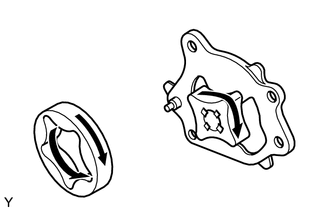
Apply a sufficient amount of engine oil to the positions indicated in the illustration, then check for any foreign matter. Install the drive gear and driven rotor.
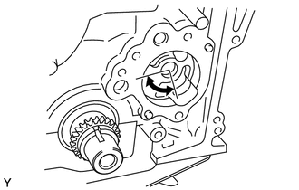
Apply a sufficient amount of engine oil to the position indicated in the illustration, then check for any foreign matter. Install the oil pump assembly onto the cylinder block.
After installing the oil pump assembly, turn it by more than 1 revolution. Spread engine oil all over the rotor and check that the oil pump rotates smoothly.
Install the oil pump assembly with the 3 bolts.
- Torque:
- 9.0 N*m (92 kgf*cm, 80 in.*lbf)
15708
2.INSTALL NO. 1 OIL NOZZLE SUB-ASSEMBLY
Install the No. 1 oil nozzle sub-assembly with the bolt.
- Torque:
- 7.5 N*m (77 kgf*cm, 66 in.*lbf)
13591
3.INSTALL TIMING CHAIN TENSION ARM
Install the timing chain tension arm with the bolt.
- Torque:
- 19 N*m (194 kgf*cm, 14 ft.*lbf)
13566B
4.INSTALL TIMING CHAIN GUIDE
Install the timing chain guide with the 2 bolts.
- Torque:
- 7.5 N*m (77 kgf*cm, 66 in.*lbf)
13506
5.INSTALL CHAIN SUB-ASSEMBLY
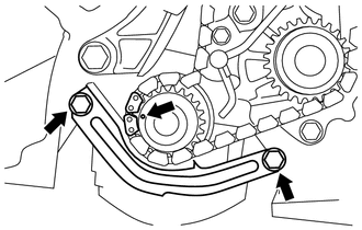
Align the yellow mark plate of the timing chain with the matchmark of the crankshaft timing sprocket as illustrated, then install the chain sub-assembly.
Install the No. 2 timing chain guide with the 2 bolts.
- Torque:
- 7.5 N*m (77 kgf*cm, 66 in.*lbf)
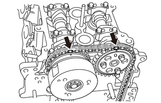
Align the yellow mark plates of the timing chain with the matchmarks of the camshaft timing sprocket and timing sprocket gear as illustrated, then install the timing chain.
13545
6.INSTALL CHAIN TENSIONER PLUNGER
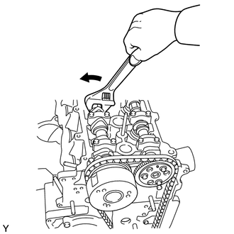
While holding the hexagonal lobe of the camshaft, slightly turn the camshaft to the left, then install the tensioner with the chain loose on the tensioner side.
Install the chain tensioner plunger with the bolt and nut.
- Torque:
- 9.0 N*m (92 kgf*cm, 80 in.*lbf)
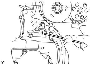
Remove the 2.5 mm (0.098 in.) diameter hexagon wrench from the tensioner.
- HINT:
-
Tension is applied to the chain.
19315
7.INSTALL NO. 1 CRANKSHAFT POSITION SENSOR PLATE
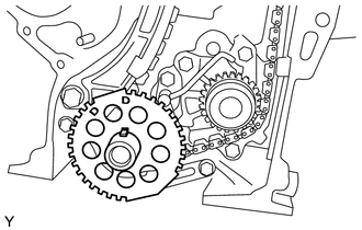
Install the No. 1 crankshaft position sensor plate with the D marks facing outward.
11302A
8.INSTALL TIMING CHAIN OR BELT COVER OIL SEAL
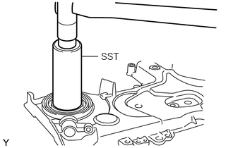
Using SST, uniformly tap in a new oil seal until its surface is flush with the timing chain or belt cover sub-assembly edge.
- SST
- 09608-06041
- Protrusion of seal from edge:
0.5 mm (0.020 in.) or less
- Depth of seal from edge:
1.0 mm (0.039 in.) or less
- NOTICE:
- ·
Do not tap in the oil seal at an angle.
·Keep the lip free of foreign matter.
Apply a light coat of multipurpose grease to the lip of the new timing chain or belt cover oil seal.
11302
9.INSTALL TIMING CHAIN OR BELT COVER SUB-ASSEMBLY
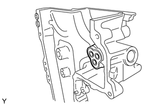
Install a new timing chain cover gasket onto the timing chain or belt cover sub-assembly.
Apply seal packing to the timing chain or belt cover sub-assembly.
- Seal packing:
Toyota Genuine Seal Packing Black, Three Bond 1207B or equivalent
- NOTICE:
- ·
Remove any oil from the contact surface.
·Install the timing chain cover within 3 minutes, and tighten the bolts within 15 minutes of applying the seal packing.
·Do not expose the seal packing to engine oil for at least 2 hours after the installation.
·Do not start the engine for at least 2 hours after the installation.
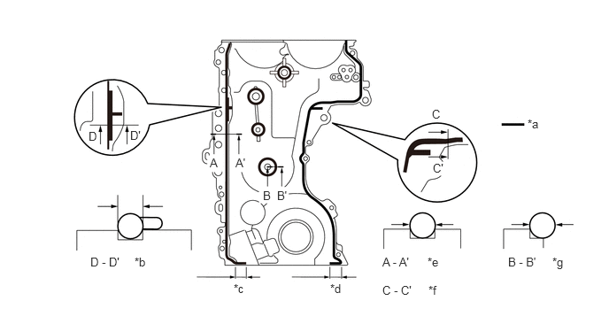
| *a | Seal Packing | *b | 6.0 mm (0.2362 in.) |
| *c | 3.0 to 4.0 mm (0.1181 to 0.1575 in.) | *d | 3.0 to 4.0 mm (0.1181 to 0.1575 in.) |
| *e | 3.0 to 4.0 mm (0.1181 to 0.1575 in.) | *f | 6.0 mm (0.2362 in.) |
| *g | 3.0 mm (0.1181 in.) | - | - |
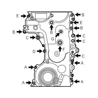
Install the timing chain or belt cover sub-assembly with the 15 bolts and nut.
- Torque:
- for bolt A : 12 N*m (122 kgf*cm, 9 ft.*lbf)
- for bolt B : 23 N*m (235 kgf*cm, 17 ft.*lbf)
- for bolt C : 44 N*m (449 kgf*cm, 32 ft.*lbf)
- for bolt D : 12 N*m (122 kgf*cm, 9 ft.*lbf)
- for bolt E : 12 N*m (122 kgf*cm, 9 ft.*lbf)
- for bolt F : 12 N*m (122 kgf*cm, 9 ft.*lbf)
- for bolt G : 44 N*m (449 kgf*cm, 32 ft.*lbf)
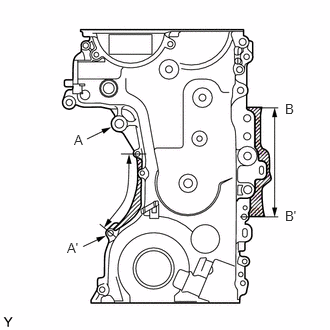
Wipe off any spilt seal packing.
- NOTICE:
- ·
Be careful when wiping off the seal packing from the area between A and A' shown in the illustration. Damage may cause coolant leaks.
·Be careful when wiping off the seal packing from the area between B and B' shown in the illustration. Excessive seal packing on this area may cause incorrect installation of the vane pump bracket.
12101
10.INSTALL OIL PAN SUB-ASSEMBLY
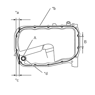
Apply seal packing to the oil pan sub-assembly.
- Specification:
Area Measurement *a 18 mm (0.709 in.) *b 3.0 to 4.0 mm (0.118 to 0.157 in.) *c 17 mm (0.669 in.) *d 1.3 to 1.5 mm (0.051 to 0.059 in.)
- Seal packing:
Toyota Genuine Seal Packing Black, Three Bond 1207B or equivalent
- NOTICE:
- ·
Make sure that seal packing does not come into contact with area A in the illustration.
·Remove any oil from the contact surface.
·Install the oil pan within 3 minutes, and tighten the bolts within 15 minutes of applying the seal packing.
·Do not expose the seal packing to engine oil for at least 2 hours after the installation.
·Do not start the engine for at least 2 hours after the installation.
·Do not begin or finish applications of seal packing near the engine front chain cover or the rear oil seal retainer. Any joints in the seal packing should be on the intake or exhaust side of the cylinder block.
·The seal packing should not protrude more than 1.5 mm (0.059 in.) beyond the transmission assembly (area B shown in the illustration).
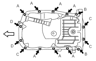

|
Engine Front |
Install the oil pan with the 11 bolts and 3 nuts.
- Torque:
- for bolt A : 8.5 N*m (87 kgf*cm, 75 in.*lbf)
- for bolt B : 42 N*m (428 kgf*cm, 31 ft.*lbf)
- for bolt C : 8.5 N*m (87 kgf*cm, 75 in.*lbf)
- for bolt D : 8.5 N*m (87 kgf*cm, 75 in.*lbf)
- HINT:
-
Each bolt length is as follows.
A: 18 mm (0.709 in.)
B: 25 mm (0.984 in.)
D: 20 mm (0.787 in.)
13471
11.INSTALL CRANKSHAFT PULLEY
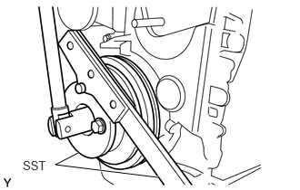
Using SST, hold the crankshaft pulley and tighten the bolt.
- SST
- 09330-00021
09213-54015 (91651-60855)
- Torque:
- 140 N*m (1428 kgf*cm, 103 ft.*lbf)
16603A
12.INSTALL NO. 1 IDLER PULLEY SUB-ASSEMBLY
Install the No. 1 idler pulley sub-assembly with the nut.
- Torque:
- 44 N*m (449 kgf*cm, 33 ft.*lbf)
16604B
13.INSTALL NO. 2 IDLER PULLEY SUB-ASSEMBLY
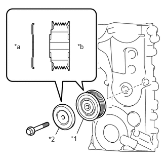
| *1 | No. 2 idler pulley sub-assembly |
| *2 | Idler pulley cover plate |
| *a | Engine Outside |
| *b | Chain Cover Side |
Install the No. 2 idler pulley sub-assembly and idler pulley cover plate with the nut.
- NOTICE:
-
Be sure to install the idler pulley cover plate in the correct orientation.
- Torque:
- 44 N*m (449 kgf*cm, 33 ft.*lbf)
16173
14.INSTALL WATER PUMP PULLEY
15330
15.INSTALL CAM TIMING OIL CONTROL VALVE ASSEMBLY
Install the cam timing oil control valve sub-assembly with the bolt.
- Torque:
- 7.5 N*m (77 kgf*cm, 66 in.*lbf)
11201
16.INSTALL CYLINDER HEAD COVER SUB-ASSEMBLY
19500
17.INSTALL IGNITION COIL ASSEMBLY
16507
18.INSTALL RADIATOR PIPE SUB-ASSEMBLY
Connect the No. 4 radiator hose.
Install the radiator pipe sub-assembly with the 2 bolts.
- Torque:
- 7.5 N*m (77 kgf*cm, 66 in.*lbf)
19.INSTALL ENGINE ASSEMBLY