3SZ-VE FUEL FUEL TANK INSTALLATION
PROCEDURE

 77201
1.INSTALL FUEL TANK INLET PIPE SUB-ASSEMBLY
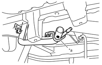
| *a | White Paint Mark |
Install the fuel tank inlet pipe sub-assembly onto the fuel tank filler pipe shield.
- HINT:
-
A white paint mark should be on the fuel tank inlet pipe sub-assembly.
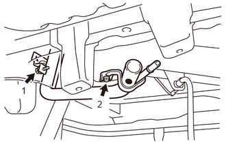
Tighten the 2 bolts in the sequence shown in the illustration.
- Torque:
- 6.5 N*m (66 kgf*cm, 58 in.*lbf)
Install the fuel tank cap assembly.
77141B
2.INSTALL NO. 1 FUEL TANK FLANGE REINFORCEMENT
Install the 4 No. 1 fuel tank flange reinforcements to the fuel tank assembly.
77380
3.INSTALL FUEL CUT OFF VALVE ASSEMBLY
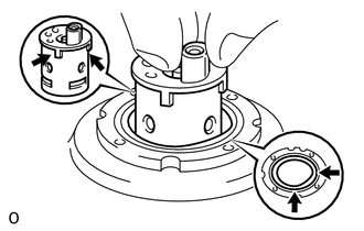
Install the fuel cut off valve assembly onto the fuel tank assembly as shown in the illustration.
77013
4.INSTALL NO. 2 FUEL TANK BREATHER TUBE SUB-ASSEMBLY
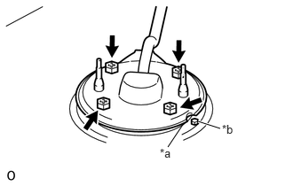
| *a | Groove |
| *b | Protrusion |
Align the protrusion of the fuel tank assembly with the groove of the No. 2 fuel tank breather tube sub-assembly, then install the No. 2 fuel tank breather tube sub-assembly with the 4 bolts.
- Torque:
- 2.0 N*m (20 kgf*cm, 18 in.*lbf)
Attach the No. 2 fuel tank breather tube sub-assembly to the fuel tank assembly.
77100B
5.INSTALL FUEL HOSE CLAMP
Engage the 4 claws to install the fuel hose clamp.
77631A
6.INSTALL CENTER LOWER FUEL TANK PROTECTOR
Install the center lower fuel tank protector with the 3 bolts.
77108B
7.INSTALL FUEL TANK FILLER CHECK VALVE SUB-ASSEMBLY
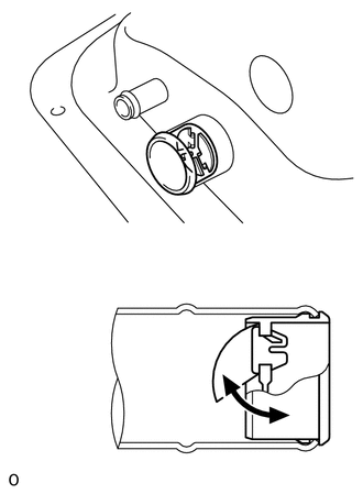
Install the fuel tank filler check valve sub-assembly as shown in the illustration.
- NOTICE:
- ·
Insert the fuel tank filler check valve sub-assembly until its claw fits into the spool.
·The valve should smoothly open and close with its own weight after installing the valve.
77269A
8.INSTALL FUEL TANK BREATHER HOSE
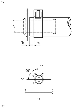
| *1 | Tank Flange |
| *a | Tank Side |
| *b | 0 to 3 mm (0 to 0.12 in.) |
| *c | 2 to 7 mm (0.08 to 0.28 in.) |
| *d | Up |
| *e | Left |
Install the fuel tank breather hose onto the fuel tank assembly.
- NOTICE:
-
Install the clip as shown in the illustration.
77213B
9.INSTALL FUEL TANK TO FILLER PIPE HOSE
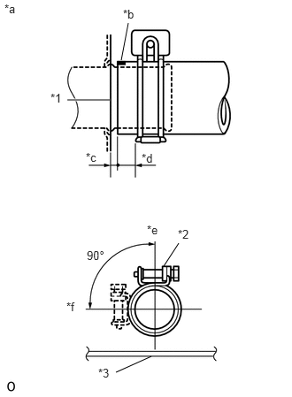
| *1 | Fuel Tank |
| *2 | Spacer |
| *3 | Tank Flange |
| *a | Tank Side |
| *b | Paint Mark |
| *c | 0 to 3 mm (0 to 0.12 in.) |
| *d | 2 to 10 mm (0.08 to 0.39 in.) |
| *e | Up |
| *f | Left |
Check that the fuel tank filler check valve sub-assembly is securely installed to the fuel tank assembly.
Install the fuel tank to filler pipe hose onto the fuel tank assembly.
- NOTICE:
- ·
Install the fuel tank to filler pipe hose so the paint mark faces upward at the fuel tank side.
·Install the hose clamp as shown in the illustration, then tighten it until it comes into contact with the spacer.
23300J
10.INSTALL FUEL FILTER ASSEMBLY
Install the fuel filter assembly with the 2 bolts.
- Torque:
- 7.0 N*m (71 kgf*cm, 62 in.*lbf)
23210P
11.INSTALL FUEL PUMP WITH MOTOR AND BRACKET ASSEMBLY
77286D
12.INSTALL NO. 2 FUEL TUBE CLAMP
Engage the guide to install the No. 2 fuel tube clamp to the fuel tank assembly.
77285D
13.INSTALL NO. 1 FUEL TUBE CLAMP
Engage the 2 claws to install the No. 1 fuel tube clamp to the fuel tank assembly.
77204A
14.INSTALL FUEL TANK RETURN TUBE SUB-ASSEMBLY
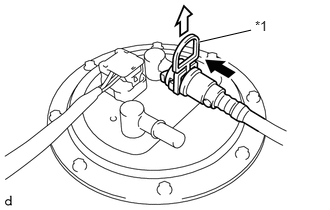
| *1 | Checker |

|
Push |

|
Pull out |
Align a new fuel tank return tube sub-assembly (fuel tube connector) with the fuel pump tube, then push in the fuel tank return tube sub-assembly until the retainer makes a click sound. Then pull out the checker.
- NOTICE:
- ·
Check that there are no scratches or foreign matter around the connected parts of the fuel pump tube and fuel tank return tube sub-assembly (fuel tube connector) before this work.
·After connecting the fuel tank return tube sub-assembly (fuel tube connector), check that the fuel pump tube and fuel tank return tube sub-assembly are securely connected by pulling them.
- HINT:
-
If connecting the tubes is too tight, apply a light coat of appropriate lubricant or gasoline to the tip of the fuel pump tube.
Attach the fuel tank return tube sub-assembly to the No. 2 fuel tube clamp.
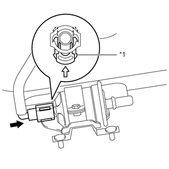
| *1 | Retainer |
|
|
Push |
|
|
Push |
Insert the fuel tank return tube sub-assembly (fuel tube connector) until it comes into contact with the fuel filter tube, then push in the retainer until it makes a click sound.
- NOTICE:
- ·
Check that there are no scratches or foreign matter around the connected parts of the fuel filter tube and fuel tank return tube sub-assembly (fuel tube connector) before this work.
·After connecting the fuel tank return tube sub-assembly (fuel tube connector), check that the fuel filter tube and fuel tank return tube sub-assembly are securely connected by pulling them.
- HINT:
-
If connecting the tubes is too tight, apply a light coat of appropriate lubricant or gasoline to the tip of the fuel filter tube.
Attach the fuel tank return tube sub-assembly to the No. 1 fuel tube clamp.
77203A
15.INSTALL FUEL SUCTION TUBE SUB-ASSEMBLY
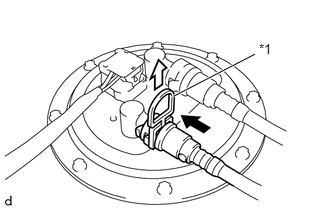
| *1 | Checker |
|
|
Push |
|
|
Pull out |
Align a new fuel suction tube sub-assembly (fuel tube connector) with the fuel pump tube, then push in the fuel suction tube sub-assembly until the retainer makes a click sound. Then pull out the checker.
- NOTICE:
- ·
Check that there are no scratches or foreign matter around the connected parts of the fuel pump tube and fuel suction tube sub-assembly (fuel tube connector) before this work.
·After connecting the fuel suction tube sub-assembly (fuel tube connector), check that the fuel pump tube and fuel suction tube sub-assembly are securely connected by pulling them.
- HINT:
-
If connecting the tubes is too tight, apply a light coat of appropriate lubricant or gasoline to the tip of the fuel pump tube.
Attach the fuel suction tube sub-assembly to the No. 2 fuel tube clamp.
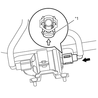
| *1 | Retainer |
|
|
Push |
|
|
Push |
Insert the fuel suction tube sub-assembly (fuel tube connector) until it comes into contact with the fuel filter tube, then push in the retainer until it makes a click sound.
- NOTICE:
- ·
Check that there are no scratches or foreign matter around the connected parts of the fuel filter tube and fuel suction tube sub-assembly (fuel tube connector) before this work.
·After connecting the fuel suction tube sub-assembly (fuel tube connector), check that the fuel filter tube and fuel suction tube sub-assembly are securely connected by pulling them.
- HINT:
-
If connecting the tubes is too tight, apply a light coat of appropriate lubricant or gasoline to the tip of the fuel filter tube.
Attach the fuel suction tube sub-assembly to the No. 1 fuel tube clamp.
87268T
16.INSTALL NO. 1 PROTECTOR
Install the No. 1 protector with the 2 nuts.
- Torque:
- 7.0 N*m (71 kgf*cm, 62 in.*lbf)
77100
17.INSTALL FUEL TANK ASSEMBLY
Operate the transmission jack to install the fuel tank assembly onto the vehicle.
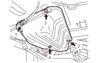
Tighten the 4 bolts in the sequence shown in the illustration.
- Torque:
- 32 N*m (326 kgf*cm, 24 ft.*lbf)
Connect the fuel pump connector.
77269A
18.CONNECT FUEL TANK BREATHER HOSE
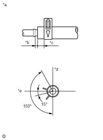
| *a | Inlet Pipe Side |
| *b | 0 to 3 mm (0 to 0.12 in.) |
| *c | 2 to 7 mm (0.08 to 0.28 in.) |
| *d | Up |
| *e | Left |
Connect the fuel tank breather hose to the fuel tank inlet pipe sub-assembly as shown in the illustration.
77213B
19.CONNECT FUEL TANK TO FILLER PIPE HOSE
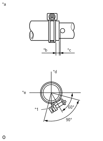
| *1 | Spacer |
| *a | Inlet Pipe Side |
| *b | 2 to 15 mm (0.08 to 0.59 in.) |
| *c | 0 to 3 mm (0 to 0.12 in.) |
| *d | Up |
| *e | Left |
Connect the fuel tank to filler pipe hose to the fuel tank inlet pipe sub-assembly as shown in the illustration.
- NOTICE:
-
Tighten the hose clamp until it comes into contact with the spacer.
77204A
20.CONNECT FUEL TANK RETURN TUBE SUB-ASSEMBLY
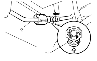
| *1 | Retainer |
| *2 | Fuel Main Tube |
|
|
Push |
|
|
Push |
Insert the fuel tank return tube sub-assembly (fuel tube connector) until it comes into contact with the fuel main tube, then push in the retainer until it makes a click sound.
- NOTICE:
- ·
Check that there are no scratches or foreign matter around the connected parts of the fuel main tube and fuel tank return tube sub-assembly (fuel tube connector) before this work.
·After connecting the fuel tank return tube sub-assembly (fuel tube connector), check that the fuel main tube and fuel tank return tube sub-assembly are securely connected by pulling them.
- HINT:
-
If connecting the tubes is too tight, apply a light coat of appropriate lubricant or gasoline to the tip of the fuel main tube.
77259C
21.CONNECT FUEL HOSE
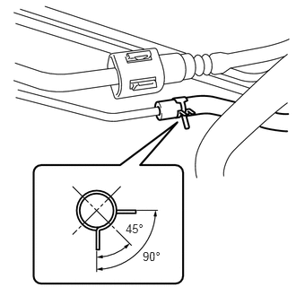
Connect the fuel hose to the fuel tank to canister tube with the clip as shown in the illustration.
37100
22.TEMPORARILY TIGHTEN PROPELLER SHAFT ASSEMBLY
37100
23.FULLY TIGHTEN PROPELLER SHAFT ASSEMBLY
24.ADD FUEL
25.INSPECT FOR OIL LEAK
26.INSPECT FOR FUEL LEAK