Home › Vehicle Interior › LIGHTING (INT) › LIGHTING SYSTEM › from 2015.08
RM19Y0E _58 Vehicle Interior _003007 LIGHTING (INT) _0015198 LIGHTING SYSTEM J

LIGHTING (INT)  LIGHTING SYSTEM  Key Warning Switch Circuit  


WIRING DIAGRAM
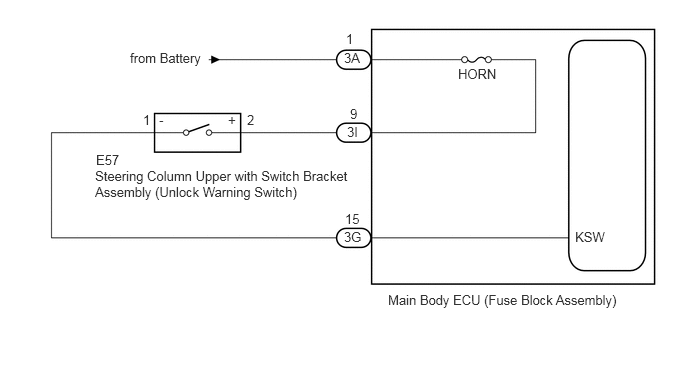
E322665E02
1.354,0.521 2.396,0.865 1.042,0.344 10 false from Battery 0.99,1.75 3.688,2.354 2.698,0.604 10 false Steering Column Upper with Switch Bracket Assembly (Unlock Warning Switch) 4.771,0.688 5.385,1.031 0.615,0.344 10 false HORN 5.99,2.385 6.563,2.719 0.573,0.333 10 false KSW 3.583,0.521 4.104,1.042 0.521,0.521 10 false 3A 3.604,0.323 3.865,0.521 0.26,0.198 10 false 1 3.646,1.104 3.906,1.302 0.26,0.198 10 false 9 3.615,1.292 3.875,1.49 0.26,0.198 10 false 3I 3.594,2.198 3.854,2.396 0.26,0.198 10 false 15 3.583,2.385 3.844,2.583 0.26,0.198 10 false 3G 4.042,3.042 6.979,3.802 2.938,0.76 10 false Main Body ECU (Fuse Block Assembly) 1.656,1.167 1.917,1.365 0.26,0.198 10 false - 2.573,1.167 2.833,1.365 0.26,0.198 10 false 2 1.49,1.167 1.75,1.365 0.26,0.198 10 false 1 2.375,1.167 2.635,1.365 0.26,0.198 10 false + 1,1.583 4.26,2.99 3.26,1.406 10 false E57

CAUTION / NOTICE / HINT

NOTICE:

Inspect the fuses for circuits related to this system before performing the following procedure.


PROCEDURE

1.READ VALUE USING GTS OR TECHSTREAM (KEY SW)
a.

Connect the GTS or Techstream to the DLC3.


b.

Turn the ignition switch to ON.


c.

Turn the GTS or Techstream on.


d.

Enter the following menus: Body Electrical / Body / Data List.


e.

Read the display on the GTS or Techstream.

Body Electrical / Body / Data List
Tester Display Measurement Item Range Normal Condition Diagnostic Note
KEY SW Key switch on signal ON or OFF ON: Key is inserted into ignition key cylinder
OFF: Key is removed from ignition key cylinder
-

OK:

Normal conditions listed above are displayed.


Result:
Proceed to
OK
NG


OK

PROCEED TO NEXT SUSPECTED AREA SHOWN IN PROBLEM SYMPTOMS TABLE

NG

2.INSPECT STEERING COLUMN UPPER WITH SWITCH BRACKET ASSEMBLY (UNLOCK WARNING SWITCH)
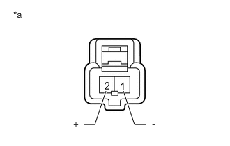
E238717C05
1.25,1.865 1.417,1.865 1.417,1.865 1.583,1.365 true 2.177,1.865 2.01,1.865 2.01,1.865 1.844,1.365 true 0.198,0.135 0.573,0.531 0.375,0.396 10 false *a 1.094,1.781 1.552,2.083 0.458,0.302 10 false + 2.271,1.771 2.646,2.104 0.375,0.333 10 false -
*a Component without harness connected
(Steering Column Upper with Switch Bracket Assembly (Unlock Warning Switch))


a.

Disconnect the E57 steering column upper with switch bracket assembly (unlock warning switch) connector.

b.

Measure the resistance according to the value(s) in the table below.

Standard Resistance:
Tester Connection Condition Specified Condition
1 (-) - 2 (+) No key in ignition key cylinder 10 kΩ or higher
1 (-) - 2 (+) Key inserted into ignition key cylinder Below 1 Ω


Result:
Proceed to
OK
NG


OK

3.CHECK HARNESS AND CONNECTOR (MAIN BODY ECU (FUSE BLOCK ASSEMBLY) - BATTERY)

NG

REPLACE STEERING COLUMN UPPER WITH SWITCH BRACKET ASSEMBLY (UNLOCK WARNING SWITCH)

3.CHECK HARNESS AND CONNECTOR (MAIN BODY ECU (FUSE BLOCK ASSEMBLY) - BATTERY)
a.
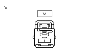
E323364C01
1.5,0.417 2.083,0.667 0.583,0.25 0.156,0.219 0.469,0.375 0.313,0.156 10 false *a 1.688,0.469 2,0.667 0.313,0.198 10 false 3A
*a Component without harness connected
(to Main Body ECU (Fuse Block Assembly) connector)


Measure the voltage according to the value(s) in the table below.

Standard Voltage:
Tester Connection Condition Specified Condition
3A-1 - Body ground Always 11 to 14 V


Result:
Proceed to
OK
NG


OK

4.CHECK HARNESS AND CONNECTOR (MAIN BODY ECU (FUSE BLOCK ASSEMBLY) - STEERING COLUMN UPPER WITH SWITCH BRACKET (UNLOCK WARNING SWITCH))

NG

REPAIR OR REPLACE HARNESS OR CONNECTOR

4.CHECK HARNESS AND CONNECTOR (MAIN BODY ECU (FUSE BLOCK ASSEMBLY) - STEERING COLUMN UPPER WITH SWITCH BRACKET (UNLOCK WARNING SWITCH))
a.

Disconnect the E57 steering column upper with switch bracket assembly (unlock warning switch) connector.


b.
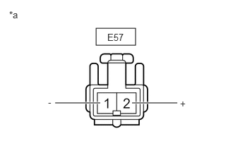
E237443C03
1.417,0.417 2,0.667 0.583,0.25 1.948,1.521 2.615,1.521 true 0.813,1.521 1.479,1.521 true 0.135,0.135 0.448,0.333 0.313,0.198 10 false *a 1.583,0.469 2.042,0.667 0.458,0.198 10 false E57 2.656,1.448 2.969,1.646 0.313,0.198 10 false + 0.708,1.427 1.021,1.625 0.313,0.198 10 false -
*a Front view of wire harness connector (to Steering Column Upper with Switch Bracket Assembly (Unlock Warning Switch))


Measure the voltage according to the value(s) in the table below.

Standard Voltage:
Tester Connection Condition Specified Condition
E57-2 (+) - Body ground Always 11 to 14 V


c.

Disconnect the 3I and 3G main body ECU (fuse block assembly) connector.


d.

Measure the resistance according to the value(s) in the table below.

Standard Resistance (Check for Open):
Tester Connection Condition Specified Condition
3I-9 - E57-2 (+) Always Below 1 Ω
3G-15 - E57-1 (-) Always Below 1 Ω


Standard Resistance (Check for Short):
Tester Connection Condition Specified Condition
3I-9 or E57-2 (+) - Body ground Always 10 kΩ or higher
3G-15 or E57-1 (-) - Body ground Always 10 kΩ or higher


Result:
Result Proceed to
OK (for RHD) A
OK (for LHD) B
NG C


A

REPLACE MAIN BODY ECU (FUSE BLOCK ASSEMBLY)

B

REPLACE MAIN BODY ECU (FUSE BLOCK ASSEMBLY)

C

REPAIR OR REPLACE HARNESS OR CONNECTOR