Home › Vehicle Exterior › WINDOW / GLASS › POWER WINDOW CONTROL SYSTEM › from 2015.08
RM19Y0E _59 Vehicle Exterior _003016 WINDOW / GLASS _0015247 POWER WINDOW CONTROL SYSTEM J

WINDOW / GLASS  POWER WINDOW CONTROL SYSTEM  Front Passenger Side Power Window does not Operate with Front Passenger Side Power Window Switch  


DESCRIPTION

If the front passenger side manual up/down function does not operate, a malfunction may exist in the power window regulator motor assembly LH*1 or RH*2 (for front side), power window regulator switch assembly (for front passenger side), power window regulator master switch assembly or wire harness.

*1: for RHD

*2: for LHD


WIRING DIAGRAM
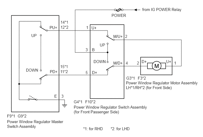
E322676E06
1.104,1.167 2.094,2.052 0.99,0.885 10 false UP 0.917,2.385 2.073,3.521 1.156,1.135 10 false DOWN 1.75,0.885 2.906,1.896 1.156,1.01 10 false PU+ 1.76,2.438 2.813,3.417 1.052,0.979 10 false PD+ 1.917,3.302 3.042,4.063 1.125,0.76 10 false E 0.25,4 1.688,4.438 1.438,0.438 10 false F9*1 0.25,4.198 2.292,4.813 2.042,0.615 10 false Power Window Regulator Master Switch Assembly 2.135,0.698 3.333,1.677 1.198,0.979 10 false 14*1 2.125,2.26 3.115,3.188 0.99,0.927 10 false 15*1 2.167,3.302 2.479,3.5 0.313,0.198 10 false 3 3.042,0.885 4.042,1.823 1,0.938 10 false 1 3.021,1.667 3.865,2.292 0.844,0.625 10 false 3 3.021,2.469 4.323,3.563 1.302,1.094 10 false 5 3.521,1.5 4.969,2.552 1.448,1.052 10 false UP 3.302,2.083 4.563,3.083 1.26,1 10 false DOWN 3.229,0.896 3.99,1.604 0.76,0.708 10 false U+ 3.25,1.667 4.333,2.625 1.083,0.958 10 false B 3.25,2.469 4.615,3.281 1.365,0.813 10 false D+ 3.01,3.5 4.052,3.948 1.042,0.448 10 false F10*2 2.604,3.688 5.26,4.281 2.656,0.594 10 false Power Window Regulator Switch Assembly (for Front Passenger Side) 4,1.198 5.531,2.115 1.531,0.917 10 false M/U+ 4,2.135 4.615,2.333 0.615,0.198 10 false M/D+ 4.417,1.198 5.063,1.719 0.646,0.521 10 false 2 4.438,2.135 5.208,2.99 0.771,0.854 10 false 4 4.833,2.135 5.604,2.927 0.771,0.792 10 false 2 6.146,2.135 7.042,2.948 0.896,0.813 10 false 1 4.458,2.667 5.823,3.385 1.365,0.719 10 false G3*1 4.448,2.833 7.042,3.604 2.594,0.771 10 false Power Window Regulator Motor Assembly LH*1/RH*2 (for Front Side) 3.938,0.458 5.604,1.427 1.667,0.969 10 false POWER 5.021,0.25 6.667,0.948 1.646,0.698 10 false from IG POWER Relay 5.865,2.083 6.667,3 0.802,0.917 10 false U+ 5,2.083 5.938,2.75 0.938,0.667 10 false D+ 2.135,0.875 3.24,1.698 1.104,0.823 10 false 12*2 2.125,2.438 3.573,3.406 1.448,0.969 10 false 11*2 0.625,4 1.938,4.479 1.313,0.479 10 false G9*2 2.604,3.5 3.635,3.917 1.031,0.417 10 false G4*1 4.865,2.667 6.188,3.438 1.323,0.771 10 false F3*2 2.938,4.448 3.938,4.813 1,0.365 10 false *1: for RHD 3.906,4.448 4.906,4.813 1,0.365 10 false *2: for LHD

CAUTION / NOTICE / HINT

NOTICE:

Inspect the fuses for circuits related to this system before performing the following inspection procedure.


PROCEDURE
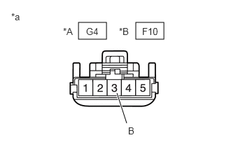
1.CHECK POWER WINDOW REGULATOR SWITCH ASSEMBLY (FOR FRONT PASSENGER SIDE) (POWER SOURCE)
a.
B398804C04
1.167,0.333 1.583,0.583 0.417,0.25 2.021,0.333 2.438,0.583 0.417,0.25 1.885,1.833 1.74,1.385 true 0.167,0.167 0.479,0.323 0.313,0.156 10 false *a 1.281,0.385 1.76,0.833 0.479,0.448 10 false G4 1.906,1.865 2.292,2.177 0.385,0.313 10 false B 0.938,0.385 1.323,0.698 0.385,0.313 10 false *A 2.115,0.385 2.594,0.823 0.479,0.438 10 false F10 1.771,0.385 2.219,0.792 0.448,0.406 10 false *B
*A for RHD
*B for LHD
*a Front view of wire harness connector
(to Power Window Regulator Switch Assembly (for Front Passenger Side))


Disconnect the G4*1 or F10*2 power window regulator switch assembly (for front passenger side) connector.

*1: for RHD

*2: for LHD


b.

Measure the voltage according to the value(s) in the table below.

Standard Voltage:
for RHD
Tester Connection Switch Condition Specified Condition
G4-3 (B) - Body ground Ignition switch ON 11 to 14 V

for LHD
Tester Connection Switch Condition Specified Condition
F10-3 (B) - Body ground Ignition switch ON 11 to 14 V


Result:
Proceed to
OK
NG


OK

2.INSPECT POWER WINDOW REGULATOR SWITCH ASSEMBLY (FOR FRONT PASSENGER SIDE)

NG

REPAIR OR REPLACE HARNESS OR CONNECTOR

2.INSPECT POWER WINDOW REGULATOR SWITCH ASSEMBLY (FOR FRONT PASSENGER SIDE)
a.

Remove the power window regulator switch assembly (for front passenger side).

Click hereVehicle Exterior>WINDOW / GLASS>FRONT PASSENGER SIDE POWER WINDOW SWITCH>REMOVAL


b.

Inspect the power window regulator switch assembly (for front passenger side).

Click hereVehicle Exterior>WINDOW / GLASS>FRONT PASSENGER SIDE POWER WINDOW SWITCH>INSPECTION

Result:
Proceed to
OK
NG


OK

3.CHECK HARNESS AND CONNECTOR (POWER WINDOW REGULATOR SWITCH ASSEMBLY (FRONT PASSENGER SIDE) - POWER WINDOW REGULATOR MOTOR ASSEMBLY (FRONT SIDE))

NG

REPLACE POWER WINDOW REGULATOR SWITCH ASSEMBLY (FOR FRONT PASSENGER SIDE)

3.CHECK HARNESS AND CONNECTOR (POWER WINDOW REGULATOR SWITCH ASSEMBLY (FRONT PASSENGER SIDE) - POWER WINDOW REGULATOR MOTOR ASSEMBLY (FRONT SIDE))
a.

Disconnect the G4*1 or F10*2 power window regulator switch assembly (for front passenger side) connector.


b.

Disconnect the G3*1 or F3*2 power window regulator motor assembly LH*1 or RH*2 (for front side) connector.


*1: for RHD

*2: for LHD


c.

Measure the resistance according to the value(s) in the table below.

Standard Resistance:
for RHD
Tester Connection Condition Specified Condition
G4-2 (M/U+) - G3-1 (U+) Always Below 1 Ω
G4-4 (M/D+) - G3-2 (D+) Always Below 1 Ω
G4-2 (M/U+) or G3-1 (U+) - Body ground Always 10 kΩ or higher
G4-4 (M/D+) or G3-2 (D+) - Body ground Always 10 kΩ or higher

for LHD
Tester Connection Condition Specified Condition
F10-2 (M/U+) - F3-1 (U+) Always Below 1 Ω
F10-4 (M/D+) - F3-2 (D+) Always Below 1 Ω
F10-2 (M/U+) or F3-1 (U+) - Body ground Always 10 kΩ or higher
F10-4 (M/D+) or F3-2 (D+) - Body ground Always 10 kΩ or higher


Result:
Proceed to
OK
NG


OK

4.INSPECT POWER WINDOW REGULATOR MOTOR ASSEMBLY (FOR FRONT SIDE)

NG

REPAIR OR REPLACE HARNESS OR CONNECTOR

4.INSPECT POWER WINDOW REGULATOR MOTOR ASSEMBLY (FOR FRONT SIDE)
a.

Remove the power window regulator motor assembly.

Click hereVehicle Exterior>WINDOW / GLASS>POWER WINDOW REGULATOR MOTOR(for Front Door)>REMOVAL


b.

Inspect the power window regulator motor assembly.

Click hereVehicle Exterior>WINDOW / GLASS>POWER WINDOW REGULATOR MOTOR(for Front Door)>INSPECTION


Result:
Result Proceed to
OK A
NG (for RHD) B
NG (for LHD) C


A

5.CHECK HARNESS AND CONNECTOR (POWER WINDOW REGULATOR MASTER SWITCH ASSEMBLY - POWER WINDOW REGULATOR SWITCH ASSEMBLY (FOR FRONT PASSENGER SIDE))

B

REPLACE POWER WINDOW REGULATOR MOTOR ASSEMBLY LH (FOR FRONT SIDE)

C

REPLACE POWER WINDOW REGULATOR MOTOR ASSEMBLY RH (FOR FRONT SIDE)

5.CHECK HARNESS AND CONNECTOR (POWER WINDOW REGULATOR MASTER SWITCH ASSEMBLY - POWER WINDOW REGULATOR SWITCH ASSEMBLY (FOR FRONT PASSENGER SIDE))
a.

Disconnect the F9*1 or G9*2 power window regulator master switch assembly connector.


b.

Disconnect the G4*1 or F10*2 power window regulator switch assembly (for front passenger side) connector.

*1: for RHD

*2: for LHD


c.

Measure the resistance according to the value(s) in the table below.

Standard Resistance:
for RHD
Tester Connection Condition Specified Condition
F9-14 (PU+) - G4-1 (U+) Always Below 1 Ω
F9-15 (PD+) - G4-5 (D+) Always Below 1 Ω
F9-14 (PU+) or G4-1 (U+) - Body ground Always 10 kΩ or higher
F9-15 (PD+) or G4-5 (D+) - Body ground Always 10 kΩ or higher

for LHD
Tester Connection Condition Specified Condition
G9-12 (PU+) - F10-1 (U+) Always Below 1 Ω
G9-11 (PD+) - F10-5 (D+) Always Below 1 Ω
G9-12 (PU+) or F10-1(U+) - Body ground Always 10 kΩ or higher
G9-12 (PD+) or F10-5 (D+) - Body ground Always 10 kΩ or higher


Result:
Proceed to
OK
NG


OK

REPLACE POWER WINDOW REGULATOR MASTER SWITCH ASSEMBLY

NG

REPAIR OR REPLACE HARNESS OR CONNECTOR