A4R AUTOMATIC TRANSMISSION / TRANSAXLE AUTOMATIC TRANSMISSION SYSTEM P0710 Transmission Fluid Temperature Sensor "A" Circuit P0711 Transmission Fluid Temperature Sensor Circuit Range / Performance
DESCRIPTION
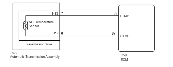
The ATF (Automatic Transmission Fluid) temperature sensor converts the fluid temperature into a resistance value which is input to the ECM.
The sensor resistance changes with the transmission fluid temperature. As the temperature rises, the sensor resistance decreases. The ECM applies a voltage to the temperature sensor through ECM terminal OTMP, and the ECM calculates the fluid temperature based on the voltage signal.
- HINT:
-
The ATF temperature is likely to increase under conditions such as towing, climbing hills and in heavy traffic.
| DTC No. | Detection Item | DTC Detection Condition | Trouble Area | MIL | Warning Indicate | Memory | Note |
|---|---|---|---|---|---|---|---|
| P0710 | Transmission Fluid Temperature Sensor "A" Circuit | 1. Diagnosis Condition 2. Malfunction Status 3. Malfunction Time 4. Other
1.
Ignition switch ON and shift lever not in P or N 2.
The transmission wire (ATF temperature sensor) output voltage is 0.15 V or lower, or 4.90 V or higher. 3.
0.5 seconds 4.
1-trip detection logic |
·
Open or short in ATF temperature sensor circuit ·
Transmission wire (ATF temperature sensor) ·
ECM |
Come on | Blinks | DTC stored | - |
| P0711 | Transmission Fluid Temperature Sensor Circuit Range / Performance | 1. Diagnosis Condition 2. Malfunction Status 3. Malfunction Time 4. Other
1.
Ignition switch ON and shift lever not in P or N 2.
Fluid temperature not increased when ignition switch is ON, even after engine warm-up. 3.
0.5 seconds 4.
1-trip detection logic |
·
Transmission wire (ATF temperature sensor) ·
ECM |
Come on | Blinks | DTC stored | - |
MIL:"Comes on" means the MIL (Malfunction Indicator Light) illuminates.
Memory:"DTC stored" means the ECM stores the trouble code if the ECU detects the DTC detection condition.
WIRING DIAGRAM
PROCEDURE
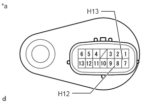
| *a | Component without harness connected
(Transmission Wire) |
Disconnect the C45 transmission wire connector.
Measure the resistance according to the value(s) in the table below.
- Standard Resistance:
Tester Connection Condition(ATF Temperature) Specified Condition 8 (H12) - 7 (H13) 20°C (68°F) Approx. 2.4 kΩ 80°C (176°F) Approx. 0.315 kΩ 8 (H12) or 7 (H13) - Body ground Always 10 kΩ or higher
- HINT:
-
If the resistance is outside the specified range at either of the ATF temperatures shown in the table below, the driveability of the vehicle may be affected.
Reconnect the C45 transmission wire connector.
- Result:
Proceed to OK NG
OK
NG
Disconnect the C50 ECM connector.
Measure the resistance according to the value(s) in the table below.
- Standard Resistance:
Tester Connection Condition(ATF Temperature) Specified Condition C50-89 (ETMP) - C45-7 (H13) Always Below 1 Ω C50-67 (OTMP) - C45-8 (H12) Always Below 1 Ω C50-89 (ETMP) or C45-7 (H13) - Body ground Always 10 kΩ or higher C50-67 (OTMP) or C45-8 (H12) - Body ground Always 10 kΩ or higher
- HINT:
-
If the resistance is outside the specified range at either of the ATF temperatures shown in the table below, the driveability of the vehicle may be affected.
Reconnect the C50 ECM connector.
- Result:
Result Proceed to OK (for 1NR-VE) A OK (for 2NR-VE) B NG C
A
B
C