RM19Y0E
_58
Vehicle Interior
_003006
THEFT DETERRENT / KEYLESS ENTRY
_0015195
THEFT DETERRENT SYSTEM
J
THEFT DETERRENT / KEYLESS ENTRY THEFT DETERRENT SYSTEM Horn Circuit
DESCRIPTION
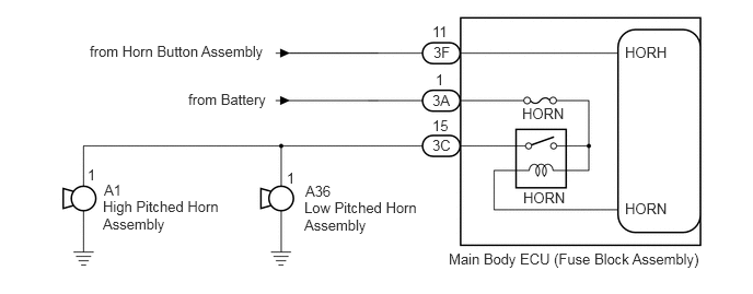
When the theft deterrent system is changed from the armed state to the alarm sounding state, the main body ECU (fuse block assembly) turns on the HORN relay so that the horns can sound. The horns sound at a cycle of 0.5 seconds.
WIRING DIAGRAM
4.271,2.385 6.896,2.771
2.625,0.385
10
false
Main Body ECU (Fuse Block Assembly)
4.969,1 5.719,1.375
0.75,0.375
10
false
HORN
4.979,1.802 5.729,2.177
0.75,0.375
10
false
HORN
5.948,1.906 6.698,2.281
0.75,0.375
10
false
HORN
5.948,0.417 6.698,0.792
0.75,0.375
10
false
HORH
4.125,0.417 4.49,0.729
0.365,0.313
10
false
3F
4.115,0.875 4.479,1.188
0.365,0.313
10
false
3A
4.115,1.302 4.479,1.615
0.365,0.313
10
false
3C
4.115,0.219 4.479,0.531
0.365,0.313
10
false
11
4.146,0.677 4.51,0.99
0.365,0.313
10
false
1
4.115,1.115 4.479,1.427
0.365,0.313
10
false
15
0.99,1.729 1.521,2.073
0.531,0.344
10
false
A1
2.906,1.74 3.438,2.083
0.531,0.344
10
false
A36
0.833,1.583 1.198,1.896
0.365,0.313
10
false
1
2.729,1.615 3.094,1.927
0.365,0.313
10
false
1
0.979,1.885 2.115,2.521
1.135,0.635
10
false
High Pitched Horn Assembly
2.896,1.896 4.031,2.531
1.135,0.635
10
false
Low Pitched Horn Assembly
1.792,0.865 2.875,1.25
1.083,0.385
10
false
from Battery
0.854,0.406 2.906,0.896
2.052,0.49
10
false
from Horn Button Assembly
CAUTION / NOTICE / HINT
- NOTICE:
-
Inspect the fuses for circuits related to this system before performing the following procedure.
PROCEDURE
1.PERFORM ACTIVE TEST USING GTS OR TECHSTREAM (HORN)
a.
Connect the GTS or Techstream to the DLC3.
b.
Turn the ignition switch to ON.
c.
Turn the GTS or Techstream on.
d.
Enter the following menus: Body Electrical / Body / Active Test.
e.
Perform the Active Test according to the display on the GTS or Techstream.
| Tester Display | Measurement Item | Control Range | Diagnostic Note |
|---|---|---|---|
| Horn | Horn | OFF/ON | - |
- Result:
Result Proceed to Horns sound A Horns do not sound B
A
PROCEED TO NEXT SUSPECTED AREA SHOWN IN PROBLEM SYMPTOMS TABLE
Click hereVehicle Interior>THEFT DETERRENT / KEYLESS ENTRY>THEFT DETERRENT SYSTEM>PROBLEM SYMPTOMS TABLE
B
2.INSPECT HORN SYSTEM
2.INSPECT HORN SYSTEM
a.
Press the horn button assembly and check if the horns sound.
- Result:
Result Proceed to Horns do not sound A Horns sound (for LHD) B Horns sound (for RHD) C
A
B
REPLACE MAIN BODY ECU (FUSE BLOCK ASSEMBLY)
C
REPLACE MAIN BODY ECU (FUSE BLOCK ASSEMBLY)