THEFT DETERRENT / KEYLESS ENTRY THEFT DETERRENT SYSTEM Security Indicator Light Circuit
DESCRIPTION
When the theft deterrent system has been set, the security indicator turns on for 0.2 seconds and off for 1.8 seconds repeatedly. In this way, the security indicator blinks. Once the alarm has been set off (the theft deterrent system has entered the alarm sounding state), the security indicator stops blinking and remains ON.
- Reference:
State of Theft Deterrent System Security Indicator Condition Disarmed state OFF Armed state Blinking Alarm sounding state ON
WIRING DIAGRAM
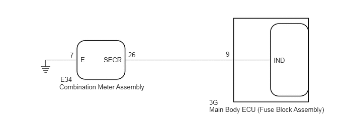
PROCEDURE
Disconnect the E34 combination meter assembly connector.
Measure the resistance according to the value(s) in the table below.
- Standard Resistance:
Tester Connection Condition Specified Condition E34-7 (E) - Body ground Always Below 1 Ω
- Result:
Proceed to OK NG
OK
NG
Disconnect the E34 combination meter assembly connector.
Disconnect the 3G main body ECU (fuse block assembly) connector.
Measure the resistance according to the value(s) in the table below.
- Standard Resistance (Check for Open):
Tester Connection Condition Specified Condition E34-26 (SECR) - 3G-9 Always Below 1 Ω
- Standard Resistance (Check for Short):
Tester Connection Condition Specified Condition E34-26 (SECR) or 3G-9 - Body ground Always 10 kΩ or higher
- Result:
Proceed to OK NG
OK
NG
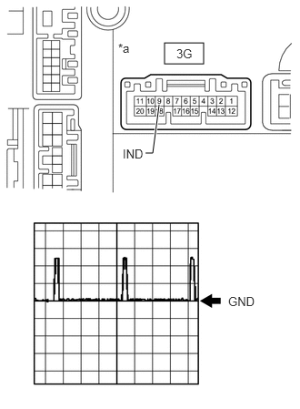
| *a | Component with harness connected
(Main Body ECU (Fuse Block Assembly)) |
Reconnect the 3G main body ECU (fuse block assembly) connector.
Using an oscilloscope, check the waveform.
- Measurement Condition:
Item Content Tester Connection 3G-9 (IND) - Body ground Tool Setting 5 V/DIV., 500 ms./DIV. Condition No key in ignition key cylinder
- OK:
Waveform is output normally (refer to illustration).
- Result:
Result Proceed to OK A NG (for LHD) B NG (for RHD) C
A
B
C