2NR-VE BATTERY / CHARGING CHARGING SYSTEM P0622 Alternator Field Duty Signal System Malfunction
DESCRIPTION
The ECM determines the battery power according to the voltage of the BATT terminal while the engine is running (not cranking).
| DTC No. | Detection Item | DTC Detection Condition | Trouble Area | Warning Indicate | Memory |
|---|---|---|---|---|---|
| P0622 | Alternator Field Duty Signal System Malfunction | Diagnosis condition: Ignition switch ON or after engine start
Abnormal condition: Detection condition 1:
·
F duty 0% ·
C terminal duty 65% or higher ·
Alternator cut control is not active Detection condition 2:
·
F duty 100% ·
Battery current is 2 A or less ·
During engine start Duration of abnormality: 2 seconds or more Number of trips: 1 trip |
·
Wire harness or connector ·
Generator assembly ·
ECM |
Charging warning light does not come on | DTC stored |
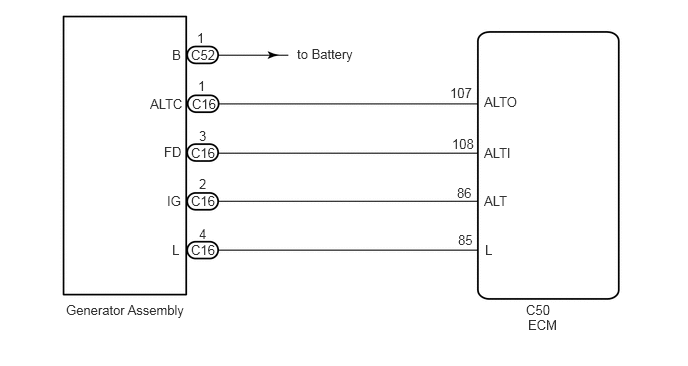
WIRING DIAGRAM
CAUTION / NOTICE / HINT
- HINT:
-
Read freeze frame data using the GTS or Techstream. The ECM records vehicle and driving condition information as freeze frame data the moment a DTC is stored.
PROCEDURE
Connect the GTS or Techstream to the DLC3.
Turn the ignition switch to ON.
Turn the GTS or Techstream on.
Enter the following menus: Powertrain / Engine and ECT / Data List.
According to the display on the GTS or Techstream, read the Data List.
| Tester Display | Measurement Item | Range | Normal Condition | Diagnostic Note |
|---|---|---|---|---|
| Alternator Output Duty | Generator output duty | Min.: 0%, Max.: 400% | Increases to a certain value, and then becomes stable:
Immediately after engine start, during idling (no electric load, air conditioner off) |
Determine ON/OFF status of alternator FD terminal and display it as a duty ratio. |
| Increases:
After engine warm-up, during idling, electric load is turned from off to on. |
- OK:
During idling, the value does not stay at 0%.
- HINT:
-
The alternator cut control may activate for a short period of time during and after the engine start. This may cause the [Alternator field duty] value to become 0%. However, this is not a malfunction.
- Result:
Proceed to OK NG
NG
OK
Click hereGeneral>INTRODUCTION>HOW TO TROUBLESHOOT ECU CONTROLLED SYSTEMS>HOW TO PROCEED WITH TROUBLESHOOTING
Remove the generator assembly.
Click herePower Source / Network>2NR-VE BATTERY / CHARGING>GENERATOR>INSPECTION
Inspect the generator assembly.
Click herePower Source / Network>2NR-VE BATTERY / CHARGING>GENERATOR>INSPECTION
- Result:
Proceed to OK NG
OK
NG
Disconnect the C16 generator assembly connector.
Disconnect the C50 ECM connector.
Measure the resistance according to the value(s) in the table below.
- Standard Resistance:
Tester Connection Condition Specified Condition C16-3 (FD) - C50-108(ALTI) Always Below 1 Ω C16-3 (FD) and C50-108(ALTI) - Body ground and other terminals Always 10 kΩ or higher
- Result:
Proceed to OK NG
OK
NG