INTERIOR PANELS / TRIM LOWER INSTRUMENT PANEL REMOVAL
CAUTION / NOTICE / HINT
- HINT:
-
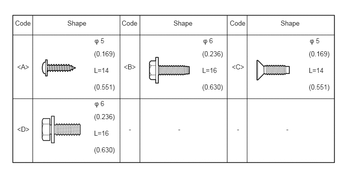
All bolts, screws and nuts relevant to installing and removing the instrument panel are shown along with their alphabet code in the table below.
PROCEDURE

 1. FRONT WHEELS FACING STRAIGHT AHEAD
55301
2.REMOVE INSTRUMENT PANEL SUB-ASSEMBLY
83100
3.REMOVE COMBINATION METER ASSEMBLY
4.REMOVE FRONT CONSOLE BOX
84941A
5.REMOVE SWITCH BASE
55606
6.REMOVE NO. 1 INSTRUMENT PANEL UNDER COVER SUB-ASSEMBLY
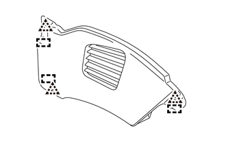
Remove the 3 clips.
Disengage the 3 guides to remove the No. 1 instrument panel under cover sub-assembly.
55608
7.REMOVE NO. 3 INSTRUMENT PANEL UNDER COVER SUB-ASSEMBLY
- HINT:
-
Use the same procedure for the No. 1 instrument panel under cover sub-assembly.
55642
8.REMOVE NO. 2 INSTRUMENT PANEL UNDER COVER
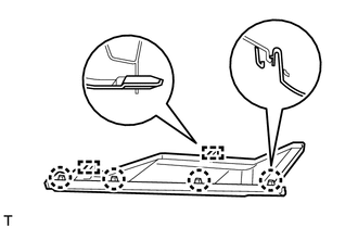
Disengage the 4 claws and 2 guides to remove the No. 2 instrument panel under cover.
55458B
9.REMOVE INSTRUMENT LOWER COVER
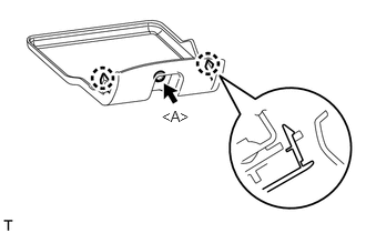
Remove the screw <A>.
Disengage the 2 claws to remove the instrument lower cover.
55476C
10.REMOVE INSTRUMENT PANEL FINISH PLATE GARNISH
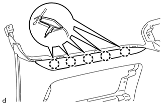
Disengage the 5 claws to remove the instrument panel finish plate garnish.
55420A
11.REMOVE CENTER INSTRUMENT CLUSTER FINISH PANEL ASSEMBLY
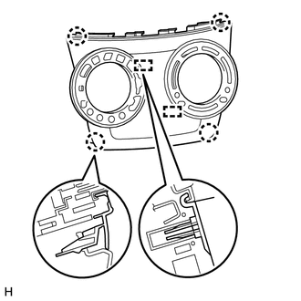
Disengage the 4 claws and 2 guides to remove the center instrument cluster finish panel assembly.
55545
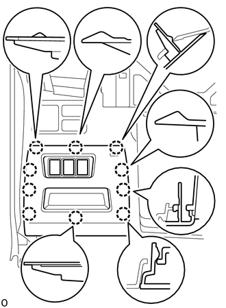
12.REMOVE FUSE BOX OPENING COVER (for LHD)
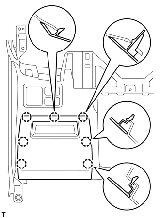
w/o VSC
Disengage the 7 claws to remove the fuse box opening cover.
w/ VSC
Disengage the 10 claws.
Disconnect each connector to remove the fuse box opening cover.
55545
13.REMOVE FUSE BOX OPENING COVER (for RHD)
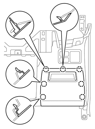
Disengage the 7 claws to remove the fuse box opening cover.
84986
14.REMOVE VEHICLE STABILITY CONTROL SWITCH (w/ VSC)
84746
15.REMOVE TIRE PRESSURE WARNING SWITCH (w/ Tire Pressure Warning System)
55539B
16.REMOVE NO. 2 SPARE SWITCH HOLE COVER (w/o Tire Pressure Warning System)
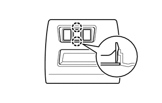
Disengage the 2 claws to remove the No. 2 spare switch hole cover.
55539D
17.REMOVE SPARE SWITCH HOLE COVER (w/o VSC)
for LHD
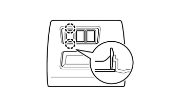
Disengage the 2 claws to remove the spare switch hole cover.
for RHD
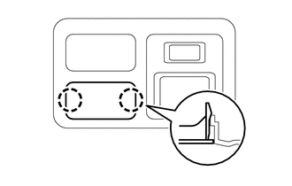
Disengage the 2 claws to remove the spare switch hole cover.
84870A
18.REMOVE OUTER MIRROR SWITCH ASSEMBLY (w/ Power Mirror Control System)
55547
19.REMOVE REMOTE CONTROL MIRROR HOLE COVER (w/o Power Mirror Control System)
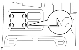
Disengage the 4 claws to remove the remote control mirror hole cover.
84790
20.REMOVE REAR WINDOW DEFOGGER SWITCH ASSEMBLY (w/ Rear Window Defogger)
55539F
21.REMOVE SPARE SWITCH HOLE COVER (w/o Rear Window Defogger)
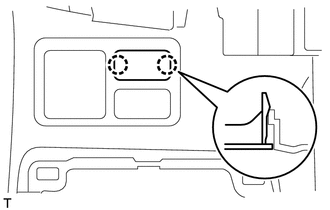
Disengage the 2 claws to remove the spare switch hole cover.
84162A
22.REMOVE REAR FOG LIGHT SWITCH (w/ Rear Fog Light)
55539N
23.REMOVE SPARE SWITCH HOLE COVER (w/o Rear Fog Light)
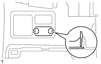
Disengage the 2 claws to remove the spare switch hole cover.
55561A
24.REMOVE GLOVE COMPARTMENT DOOR LOCK STRIKER

|
Bolt <B> |

|
Screw <A> |
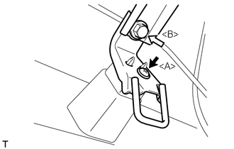
Remove the bolt <B>.
Remove the screw <A> and the glove compartment door lock striker.
55432B
25.REMOVE LOWER INSTRUMENT PANEL FINISH PANEL
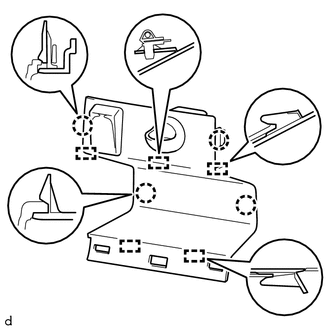
Disengage the 4 claws and 5 guides to disconnect the lower instrument panel finish panel.
Disconnect each connector.
Disengage the clamp to remove the lower instrument panel finish panel.
86190C
26.REMOVE STEREO JACK ADAPTER ASSEMBLY (w/ USB Audio System)
55539
27.REMOVE SPARE SWITCH HOLE COVER (w/o USB Audio System)
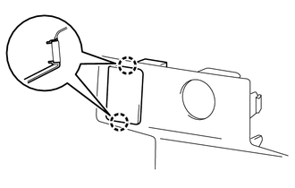
Disengage the 2 claws to remove the spare switch hole cover.
85530
28.REMOVE NO. 1 POWER OUTLET SOCKET ASSEMBLY
85535E
29.REMOVE NO. 2 POWER OUTLET SOCKET COVER
86316
30.REMOVE ANTENNA CABLE
55312
31.REMOVE LOWER INSTRUMENT PANEL
Disconnect each connector and disengage the clamp.
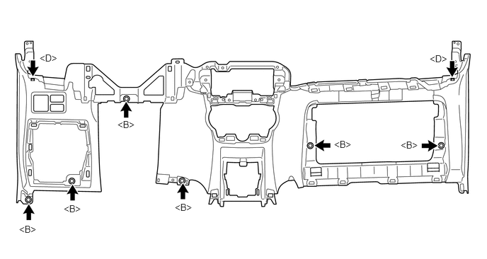
Remove the 6 bolts <B>, 2 bolts <D> and the lower instrument panel.