Home › Engine / Hybrid System › 2ZR-FXE (ENGINE CONTROL) › SFI SYSTEM
RM32K0E _51 Engine / Hybrid System _060312 2ZR-FXE ENGINE CONTROL _0295698 SFI SYSTEM J

2ZR-FXE ENGINE CONTROL  SFI SYSTEM  Fuel Injector Circuit  


DESCRIPTION

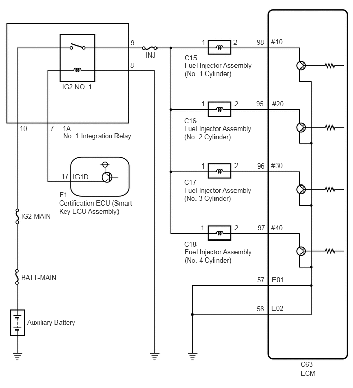
The fuel injector assemblies are located in each intake port and inject fuel into the cylinders based on the signals from the ECM.

WIRING DIAGRAM
A376213E08
5.51,0.76 5.969,0.958 0.458,0.198 10 false #10 5.531,2.021 5.99,2.219 0.458,0.198 10 false #20 5.51,3.271 5.969,3.469 0.458,0.198 10 false #30 5.51,4.531 5.969,4.729 0.458,0.198 10 false #40 5.521,5.583 5.979,5.781 0.458,0.198 10 false E01 5.51,6.167 5.969,6.365 0.458,0.198 10 false E02 5.208,0.771 5.667,0.969 0.458,0.198 10 false 98 5.198,2.021 5.656,2.219 0.458,0.198 10 false 95 5.219,3.281 5.677,3.479 0.458,0.198 10 false 96 5.229,4.531 5.688,4.729 0.458,0.198 10 false 97 5.219,5.583 5.677,5.781 0.458,0.198 10 false 57 5.208,6.177 5.667,6.375 0.458,0.198 10 false 58 6.104,7.302 6.563,7.5 0.458,0.198 10 false C63 6.104,7.479 6.563,7.677 0.458,0.198 10 false ECM 3.75,1.24 5.167,1.646 1.417,0.406 10 false Fuel Injector Assembly (No. 1 Cylinder) 3.75,1.083 4.208,1.281 0.458,0.198 10 false C15 3.74,2.521 5.167,2.927 1.427,0.406 10 false Fuel Injector Assembly (No. 2 Cylinder) 3.75,5.021 5.188,5.417 1.438,0.396 10 false Fuel Injector Assembly (No. 4 Cylinder) 3.74,2.365 4.198,2.563 0.458,0.198 10 false C16 3.74,3.615 4.198,3.813 0.458,0.198 10 false C17 3.74,4.865 4.198,5.063 0.458,0.198 10 false C18 2.958,1.031 3.417,1.229 0.458,0.198 10 false INJ 2.656,0.781 3.031,0.958 0.375,0.177 10 false 9 2.646,1.24 3.021,1.417 0.375,0.177 10 false 8 1.021,2.521 1.396,2.698 0.375,0.177 10 false 7 0.396,2.521 0.771,2.698 0.375,0.177 10 false 10 1.26,1.677 2,1.927 0.74,0.25 10 false IG2 NO. 1 1.479,3.5 2.219,3.75 0.74,0.25 10 false IG1D 1.208,3.865 1.948,4.115 0.74,0.25 10 false F1 1.198,4.031 2.729,4.563 1.531,0.531 10 false Certification ECU (Smart Key ECU Assembly) 0.427,4.302 1.167,4.552 0.74,0.25 10 false IG2-MAIN 0.427,5.542 1.208,5.802 0.781,0.26 10 false BATT-MAIN 0.552,6.448 1.74,6.781 1.188,0.333 10 false Auxiliary Battery 1.271,2.521 2.01,2.771 0.74,0.25 10 false 1A 1.281,2.667 2.813,3.198 1.531,0.531 10 false No. 1 Integration Relay 1.24,3.49 1.469,3.677 0.229,0.188 10 false 17 4.094,0.771 4.552,0.969 0.458,0.198 10 false 1 4.083,2.021 4.542,2.219 0.458,0.198 10 false 1 4.083,3.281 4.542,3.479 0.458,0.198 10 false 1 4.073,4.531 4.531,4.729 0.458,0.198 10 false 1 4.74,0.771 5.198,0.969 0.458,0.198 10 false 2 4.76,2.021 5.219,2.219 0.458,0.198 10 false 2 4.76,3.271 5.219,3.469 0.458,0.198 10 false 2 4.76,4.531 5.219,4.729 0.458,0.198 10 false 2 3.74,3.771 5.167,4.177 1.427,0.406 10 false Fuel Injector Assembly (No. 3 Cylinder)

CAUTION / NOTICE / HINT

NOTICE:

Inspect the fuses for circuits related to this system before performing the following procedure.


PROCEDURE
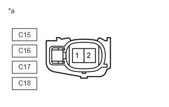
1.CHECK TERMINAL VOLTAGE (POWER SOURCE OF FUEL INJECTOR ASSEMBLY)
A395416C02
0.25,0.917 0.75,1.167 0.5,0.25 0.25,1.25 0.75,1.5 0.5,0.25 0.25,1.583 0.75,1.833 0.5,0.25 0.25,0.583 0.75,0.833 0.5,0.25 0.167,0.135 0.479,0.333 0.313,0.198 10 false *a 0.375,0.625 0.792,0.792 0.417,0.167 10 false C15 0.375,0.948 0.792,1.115 0.417,0.167 10 false C16 0.375,1.281 0.792,1.448 0.417,0.167 10 false C17 0.375,1.615 0.792,1.781 0.417,0.167 10 false C18
*a Front view of wire harness connector
(to Fuel Injector Assembly)


a.

Disconnect the fuel injector assembly connector.


b.

Turn the power switch on (IG).


c.

Measure the voltage according to the value(s) in the table below.

Standard Voltage:
Tester Connection Switch Condition Specified Condition
C15-1 - Body ground Power switch on (IG) 11 to 14 V
C16-1 - Body ground Power switch on (IG) 11 to 14 V
C17-1 - Body ground Power switch on (IG) 11 to 14 V
C18-1 - Body ground Power switch on (IG) 11 to 14 V


Result:
Proceed to
OK
NG


OK

2.INSPECT FUEL INJECTOR ASSEMBLY (INJECTION AND VOLUME)

NG

4.CHECK HARNESS AND CONNECTOR (NO. 1 INTEGRATION RELAY - FUEL INJECTOR ASSEMBLY)
2.INSPECT FUEL INJECTOR ASSEMBLY (INJECTION AND VOLUME)
a.

Inspect the fuel injector assembly.

Click hereEngine / Hybrid System>2ZR-FXE (FUEL)>FUEL INJECTOR>INSPECTION

HINT:

Perform "Inspection After Repair" after replacing the fuel injector assembly.

Click hereEngine / Hybrid System>2ZR-FXE (ENGINE CONTROL)>SFI SYSTEM>INITIALIZATION


Result:
Proceed to
OK
NG


OK

3.CHECK HARNESS AND CONNECTOR (FUEL INJECTOR ASSEMBLY - ECM)

NG

REPLACE FUEL INJECTOR ASSEMBLY

3.CHECK HARNESS AND CONNECTOR (FUEL INJECTOR ASSEMBLY - ECM)
a.

Disconnect the C15, C16, C17 and C18 fuel injector assembly connectors.


b.

Disconnect the C63 ECM connector.


c.

Measure the resistance according to the value(s) in the table below.

Standard Resistance:
Tester Connection Condition Specified Condition
C15-2 - C63-98 (#10) Always Below 1 Ω
C16-2 - C63-95 (#20) Always Below 1 Ω
C17-2 - C63-96 (#30) Always Below 1 Ω
C18-2 - C63-97 (#40) Always Below 1 Ω
C15-2 or C63-98 (#10) - Body ground and other terminals Always 10 kΩ or higher
C16-2 or C63-95 (#20) - Body ground and other terminals Always 10 kΩ or higher
C17-2 or C63-96 (#30) - Body ground and other terminals Always 10 kΩ or higher
C18-2 or C63-97 (#40) - Body ground and other terminals Always 10 kΩ or higher


Result:
Proceed to
OK
NG


OK

PROCEED TO NEXT SUSPECTED AREA SHOWN IN PROBLEM SYMPTOMS TABLE

NG

REPAIR OR REPLACE HARNESS OR CONNECTOR

4.CHECK HARNESS AND CONNECTOR (NO. 1 INTEGRATION RELAY - FUEL INJECTOR ASSEMBLY)
a.

Disconnect the 1A No. 1 integration relay connector.


b.

Disconnect the C15, C16, C17 and C18 fuel injector assembly connectors.


c.

Measure the resistance according to the value(s) in the table below.

Standard Resistance:
Tester Connection Condition Specified Condition
1A-9 - C15-1 Always Below 1 Ω
1A-9 - C16-1 Always Below 1 Ω
1A-9 - C17-1 Always Below 1 Ω
1A-9 - C18-1 Always Below 1 Ω
1A-9 or C15-1 - Body ground and other terminals Always 10 kΩ or higher
1A-9 or C16-1 - Body ground and other terminals Always 10 kΩ or higher
1A-9 or C17-1 - Body ground and other terminals Always 10 kΩ or higher
1A-9 or C18-1 - Body ground and other terminals Always 10 kΩ or higher


HINT:

If a short is detected in any of the above circuits, there may be a malfunction in the circuit of a connected ECU.


Result:
Proceed to
OK
NG


OK

NG

REPAIR OR REPLACE HARNESS OR CONNECTOR