DOOR LOCK REAR DOOR LOCK REMOVAL
CAUTION / NOTICE / HINT
The necessary procedures (adjustment, calibration, initialization, or registration) that must be performed after parts are removed and installed, or replaced during the rear door lock with motor assembly removal/installation are shown below.
| Replaced Part or Performed Procedure | Necessary Procedure | Effect/Inoperative Function when Necessary Procedure not Performed | Link |
|---|---|---|---|
| Disconnect cable from negative auxiliary battery terminal | Memorize steering angle neutral point | Lane departure alert system (w/ Steering Control) | ( ) |
| Simple intelligent parking assist system*1 | |||
| Toyota parking assist-sensor system*1 | |||
| Pre-collision System | |||
| Initialize back door lock | Power door lock control system | ()
|
|
·
Rear door glass sub-assembly ·
Rear door glass run |
Initialize Power Window Control System | ·
Auto up and down function ·
Jam protection function ·
Catch protection function ·
Remote control function ·
Key-linked function ·
Wireless transmitter-linked function ·
Key-off operation function ·
Window open warning function |
()
|
*1: When performing learning using the GTS.
- HINT:
- ·
Use the same procedure for the RH side and LH side.
·The following procedure is for the LH side.
PROCEDURE

 1. PRECAUTION
- NOTICE:
-
After turning the power switch off, waiting time may be required before disconnecting the cable from the negative (-) auxiliary battery terminal. Therefore, make sure to read the disconnecting the cable from the negative (-) auxiliary battery terminal notices before proceeding with work.
-
Click hereGeneral>INTRODUCTION>REPAIR INSTRUCTION>PRECAUTION
2.DISCONNECT CABLE FROM NEGATIVE AUXILIARY BATTERY TERMINAL
Click hereGeneral>MAINTENANCE>2ZR-FXE AUXILIARY BATTERY>REMOVAL
- NOTICE:
-
When disconnecting the cable, some systems need to be initialized after the cable is reconnected.
-
Click hereGeneral>INTRODUCTION>REPAIR INSTRUCTION>INITIALIZATION
67498
3.REMOVE REAR DOOR REAR FRAME BRACKET
69284D
4.REMOVE REAR DOOR INSIDE HANDLE BEZEL PLUG
84810D
5.REMOVE REAR POWER WINDOW REGULATOR SWITCH ASSEMBLY WITH REAR DOOR ARMREST BASE UPPER PANEL
67604
6.REMOVE REAR DOOR TRIM BOARD SUB-ASSEMBLY
67628
7.REMOVE REAR DOOR TRIM BRACKET
67842E
8.REMOVE REAR DOOR SERVICE HOLE COVER
69227L
9.REMOVE REAR DOOR OUTSIDE HANDLE COVER
69240
10.REMOVE REAR DOOR OUTSIDE HANDLE ASSEMBLY
69060A
11.REMOVE REAR DOOR LOCK WITH MOTOR ASSEMBLY
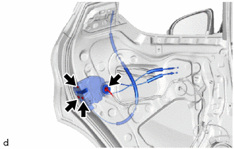
Disconnect the connector.
Using a T30 "TORX" socket wrench, remove the 3 screws and rear door lock with motor assembly.
When reusing the rear door lock with motor assembly:
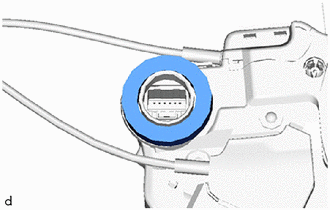
Remove the door lock wiring harness seal from the rear door lock with motor assembly.
69740D
12.REMOVE REAR DOOR LOCK REMOTE CONTROL CABLE ASSEMBLY
w/o Double Locking System:
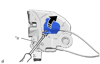
| *a | Protective Tape |

|
Remove in this Direction |
Using a screwdriver with its tip wrapped in protective tape, disengage the claw as shown in the illustration.
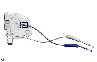
Disengage the guide to remove the rear door lock remote control cable assembly from the rear door lock with motor assembly.
w/ Double Locking System:
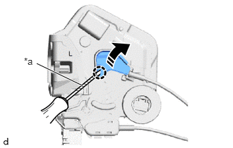
| *a | Protective Tape |
|
|
Remove in this Direction |
Using a screwdriver with its tip wrapped in protective tape, disengage the claw as shown in the illustration.
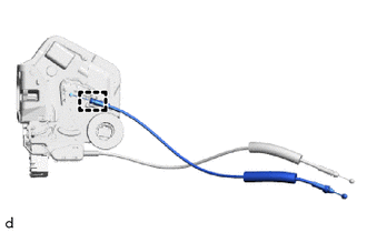
Disengage the guide to remove the rear door lock remote control cable assembly from the rear door lock with motor assembly.
69780B
13.REMOVE REAR DOOR INSIDE LOCKING CABLE ASSEMBLY
w/o Double Locking System:
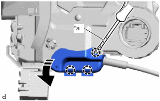
| *a | Protective Tape |
|
|
Remove in this Direction |
Using a screwdriver with its tip wrapped in protective tape, disengage the claws as shown in the illustration.
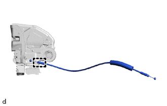
Disengage the guide to remove the rear door inside locking cable assembly from the rear door lock with motor assembly.
w/ Double Locking System:
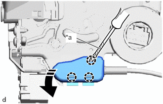
| *a | Protective Tape |
|
|
Remove in this Direction |
Using a screwdriver with its tip wrapped in protective tape, disengage the claws as shown in the illustration.
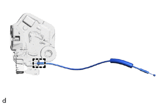
Disengage the guide to remove the rear door inside locking cable assembly from the rear door lock with motor assembly.
69730E
14.REMOVE NO. 1 REAR DOOR LOCK REMOTE CONTROL CABLE ASSEMBLY
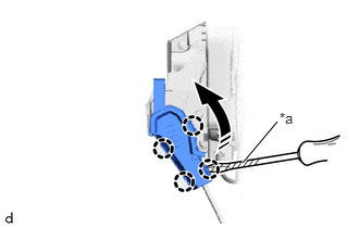
| *a | Protective Tape |
|
|
Remove in this Direction |
Using a screwdriver with its tip wrapped in protective tape, disengage the claws as shown in the illustration.
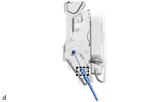
Disengage the guide to remove the No. 1 rear door lock remote control cable assembly from the rear door lock with motor assembly.