POWER DISTRIBUTION MAIN BODY ECU(for RHD) INSTALLATION
PROCEDURE

 89221
1.INSTALL MAIN BODY ECU (MULTIPLEX NETWORK BODY ECU)
- NOTICE:
- ·
Make sure that the connecting surfaces are free of foreign matter.
·Do not touch the main body ECU (multiplex network body ECU) connector.
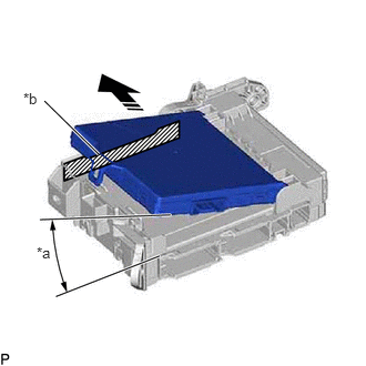
| *a | 20° or more |
| *b | Housing Sidewall |

|
Set in this Direction |
Set the main body ECU (multiplex network body ECU) to the position where the guide of the main body ECU (multiplex network body ECU) contacts the housing sidewall of the instrument panel junction block assembly as shown in the illustration.
- HINT:
-
Make sure to keep the angle at 20° or more as shown in the illustration.
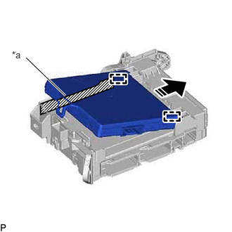
| *a | Housing Sidewall |
|
|
Slide in this Direction |
Slide the main body ECU (multiplex network body ECU) along the housing sidewall as shown in the illustration and engage the guides.
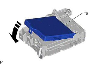
| *a | Side A |
|
|
Install in this Direction |
While keeping the main body ECU (multiplex network body ECU) in contact with side A of the instrument panel junction block assembly (axis of rotation), lower it as shown in the illustration.
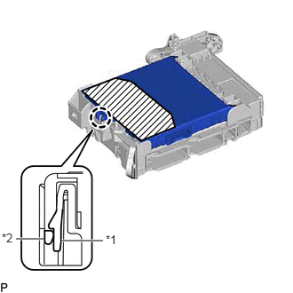
| *1 | Instrument Panel Junction Block Assembly |
| *2 | Main Body ECU (Multiplex Network Body ECU) |

|
Push Area |
Press the push area until the claw engages to install the main body ECU (multiplex network body ECU).
- NOTICE:
- ·
Make sure to press only the push area.
·Confirm the engagement of the main body ECU (multiplex network body ECU) and instrument panel junction block assembly by listening for the click sound of the lock engaging.
- HINT:
-
If a click sound cannot be heard, visually check the engagement of the lock. The engagement can also be confirmed if the main body ECU (multiplex network body ECU) and instrument panel junction block assembly are flush.
82730
2.INSTALL INSTRUMENT PANEL JUNCTION BLOCK ASSEMBLY WITH MAIN BODY ECU
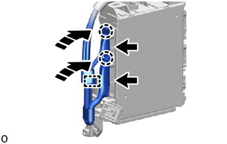
|
|
Install in this Direction |
Connect the 2 connectors and raise the 2 lock levers to engage the claws and lock the connector as shown in the illustration.
- NOTICE:
-
Be sure to connect the connector securely.
Engage the clamp.
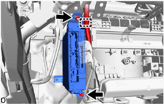
Engage the clamp.
Install the instrument panel junction block assembly with main body ECU with the bolt and nut.
- Torque:
- 8.0 N*m (82 kgf*cm, 71 in.*lbf)
Engage the clamp.
Connect the 2 connectors.
82878
3.INSTALL ECU INTEGRATION BOX LH
55433B
4.INSTALL NO. 2 INSTRUMENT PANEL LOWER FINISH PANEL
5.CONNECT CABLE TO NEGATIVE AUXILIARY BATTERY TERMINAL
for 2ZR-FXE:
Click hereGeneral>MAINTENANCE>2ZR-FXE AUXILIARY BATTERY>INSTALLATION
for M20A-FXS:
Click hereGeneral>MAINTENANCE>M20A-FXS AUXILIARY BATTERY>INSTALLATION
- NOTICE:
-
When disconnecting the cable, some systems need to be initialized after the cable is reconnected.
-
Click hereGeneral>INTRODUCTION>REPAIR INSTRUCTION>INITIALIZATION