P711 HYBRID TRANSMISSION / TRANSAXLE OIL COOLER REMOVAL
CAUTION / NOTICE / HINT
The necessary procedures (adjustment, calibration, initialization, or registration) that must be performed after parts are removed and installed, or replaced during motor cooling cooler removal/installation are shown below.
| Replaced Part or Performed Procedure | Necessary Procedure | Effect/Inoperative Function when Necessary Procedure not Performed | Link |
|---|---|---|---|
|
*1: When performing learning using the GTS. Click here( |
|||
| Auxiliary battery terminal is disconnected/reconnected | Perform steering sensor zero point calibration | Lane departure alert system (w/ Steering Control) | ( ) |
| Toyota parking assist-sensor system*1 | |||
| Parking support brake system*1 | |||
| Simple intelligent parking assist system*1 | |||
| Pre-collision system | |||
| Initialize back door lock | Power Door Lock Control System | ()
|
|
| Inverter with converter assembly | Resolver learning | ·
DTCs are stored ·
Slight vibration at a vehicle speed of 5 km/h (3 mph) or less ·
Shock or vibration during acceleration |
()
|
- CAUTION:
- ·
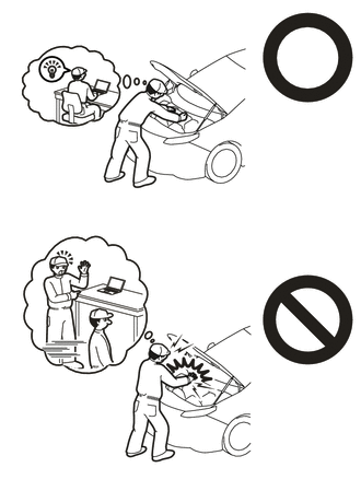
This vehicle has contains high voltage circuits standardized with orange colored wiring and connectors, so follow the instructions in this manual to perform the procedures correctly.
Click hereEngine / Hybrid System>M20A-FXS (HYBRID / BATTERY CONTROL)>HYBRID CONTROL SYSTEM>PRECAUTION
·If the correct procedures are not followed according to the instructions in this manual, there is a danger of electric shock from the high voltage circuits.
·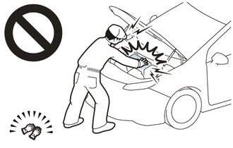
Be sure to wear insulating gloves when working on high voltage wiring or components.
·If work is performed without wearing insulating gloves, there is a danger of electric shock.
PROCEDURE

 51410
1.REMOVE NO. 1 ENGINE UNDER COVER ASSEMBLY
51444A
2.REMOVE REAR ENGINE UNDER COVER LH
G9200
3.REMOVE INVERTER WITH CONVERTER ASSEMBLY
G922H
4.DISCONNECT INLET HYBRID RADIATOR HOSE
G922F
5.DISCONNECT OUTLET NO. 1 HYBRID WATER PUMP HOSE
G125A
6.REMOVE MOTOR COOLING COOLER
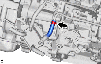
Slide the clip and disconnect the No. 1 motor cooling hose from the No. 1 motor cooling pipe.
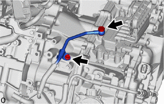
Remove the oil cooler union bolt and gasket to disconnect the No. 2 motor cooling pipe from the hybrid vehicle transaxle assembly.
Remove the bolt and No. 1 oil cooler tube clamp from the hose bracket.
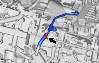
Slide the clip and remove the No. 2 motor cooling pipe from the No. 2 motor cooling hose.
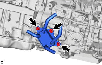
Remove the 3 bolts and motor cooling cooler from the hybrid vehicle transaxle assembly.
- NOTICE:
-
Make sure not to remove the No. 1 motor cooling hose and No. 2 motor cooling hose from the motor cooling cooler as the motor cooling cooler may be deformed.