3ZR-FAE ENGINE CONTROL SFI SYSTEM Starter Signal Circuit
DESCRIPTION
While the engine is being cranked, current flows from terminal STAR of the certification ECU (smart key ECU assembly)*1 or terminal ST2 of the ignition or starter switch assembly*2 to the park/neutral position switch and to terminal STA of the ECM (STA signal).
*1: w/ Entry and Start System
*2: w/o Entry and Start System
WIRING DIAGRAM
Refer to DTC P0617.
Click hereEngine / Hybrid System>3ZR-FAE (ENGINE CONTROL)>SFI SYSTEM>P0617
CAUTION / NOTICE / HINT
- NOTICE:
-
Inspect the fuses for circuits related to this system before performing the following inspection procedure.
PROCEDURE
Check if the engine can be cranked.
- Result:
Result Proceed to Engine cannot be cranked A Engine can be cranked B
A
B
Connect the GTS to DLC3.
Turn the ignition switch to ON.
Turn the GTS on.
Enter the following menus: Powertrain / Engine and ECT / Data List / All Data / Starter Signal.
- Powertrain > Engine and ECT > Data List
-
Tester Display Starter Signal - 50003 234 118
Check the value displayed on the GTS when the ignition switch is turned to ON and the engine is started.
- OK:
Condition GTS Display (Starter Signal) Ignition switch ON OFF Cranking position ON
- Result:
Result Proceed to OK A NG B
A
B
Inspect the ST relay.
Click hereEngine / Hybrid System>3ZR-FAE (STARTING)>RELAY>INSPECTION
- Result:
Proceed to OK NG
OK
NG
Inspect the starter assembly.
Click hereEngine / Hybrid System>3ZR-FAE (STARTING)>STARTER>INSPECTION
- Result:
Proceed to OK NG
OK
NG
Remove the ST relay from the No. 1 engine room relay block.
Disconnect the A38 ECM connector.
Measure the resistance according to the value(s) in the table below.
- Standard Resistance:
Tester Connection Condition Specified Condition 2 (ST relay holder) - A38-29 (STA) Always Below 1 Ω
- Result:
Proceed to OK NG
OK
NG
Remove the ST relay from the No. 1 engine room relay block.
Disconnect the C35 starter assembly connector.
Measure the resistance according to the value(s) in the table below.
- Standard Resistance:
Tester Connection Condition Specified Condition 3 (ST relay holder) - C35-1 Always Below 1 Ω 3 (ST relay holder) or C35-1 - Body ground and other terminals Always 10 kΩ or higher
- Result:
Proceed to OK NG
OK
NG
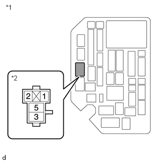
| *1 | No. 1 Engine Room Relay Block |
| *2 | ST Relay Holder |
Remove the ST relay from the No. 1 engine room relay block.
Measure the resistance according to the value(s) in the table below.
- Standard Resistance:
Tester Connection Condition Specified Condition 1 (ST relay holder) - Body ground Always Below 1 Ω
- Result:
Proceed to OK NG
OK
NG
| *1 | No. 1 Engine Room Relay Block |
| *2 | ST Relay Holder |
Remove the ST relay from the No. 1 engine room relay block.
Measure the voltage according to the value(s) in the table below.
- Standard Voltage:
Tester Connection Condition Specified Condition 5 (ST relay holder) - Body ground Always 11 to 14 V
- Result:
Proceed to OK NG
OK
NG
Inspect the park/neutral position switch.
Click hereDrivetrain>K114 (MULTIDRIVE / CVT)>PARK / NEUTRAL POSITION SWITCH>INSPECTION
- Result:
Proceed to OK NG
OK
NG
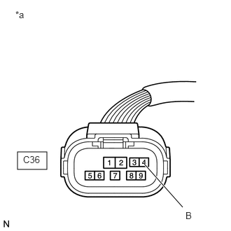
| *a | Front view of wire harness connector
(to Park/Neutral Position Switch) |
Disconnect the C36 park/neutral position switch connector.
Measure the voltage according to the value(s) in the table below.
- Standard Voltage:
Tester Connection Condition Specified Condition C36-4 (B) - Body ground Engine cranking position 11 to 14 V
- Result:
Result Proceed to OK (w/ Entry and Start System) A OK (w/o Entry and Start System) B NG (w/ Entry and Start System) C NG (w/o Entry and Start System) D
A
B
C
D
Disconnect the M66 certification ECU (smart key ECU assembly) connector.
Disconnect the C36 park/neutral position switch connector.
Remove the ST relay from the No. 1 engine room relay block.
Disconnect the A38 ECM connector.
Measure the resistance according to the value(s) in the table below.
- Standard Resistance:
Tester Connection Condition Specified Condition M66-20 (STA) - C36-9 (L) Always Below 1 Ω 2 (ST relay holder) - A38-29 (STA) Always Below 1 Ω A38-29 (STA), M66-20 (STA), 2 (ST relay holder) or C36-9 (L) - Body ground and other terminals Always 10 kΩ or higher
- Result:
Proceed to OK NG
OK
NG
Disconnect the C36 park/neutral position switch connector.
Remove the ST relay from the No. 1 engine room relay block.
Disconnect the A38 ECM connector.
Measure the resistance according to the value(s) in the table below.
- Standard Resistance:
Tester Connection Condition Specified Condition 2 (ST relay holder) - C36-9 (L) Always Below 1 Ω 2 (ST relay holder) - A38-29 (STA) Always Below 1 Ω A38-29 (STA), 2 (ST relay holder) or C36-9 (L) - Body ground and other terminals Always 10 kΩ or higher
- Result:
Proceed to OK NG
OK
NG
Disconnect the M66 certification ECU (smart key ECU assembly) connector.
Disconnect the C36 park/neutral position switch connector.
Disconnect the A38 ECM connector.
Measure the resistance according to the value(s) in the table below.
- Standard Resistance:
Tester Connection Condition Specified Condition M66-9 (STAR) - C36-4 (B) Always Below 1 Ω A38-57 (NSW), M66-9 (STAR) or C36-4 (B) - Body ground and other terminals Always 10 kΩ or higher
- Result:
Proceed to OK NG
OK
NG
Inspect the ignition or starter switch assembly.
Click hereEngine / Hybrid System>3ZR-FAE (STARTING)>IGNITION SWITCH>INSPECTION
- Result:
Proceed to OK NG
OK
NG
Disconnect the F12 ignition or starter switch assembly connector.
Measure the voltage according to the value(s) in the table below.
- Standard Voltage:
Tester Connection Condition Specified Condition F12-6 (ST1) - Body ground Always 11 to 14 V
- Result:
Proceed to OK NG
OK
NG
Connect the GTS to DLC3.
Turn the ignition switch to ON.
Turn the GTS on.
Enter the following menus: Powertrain / Engine and ECT/ Data List / All Data / Starter SW.
- Powertrain > Engine and ECT > Data List
-
Tester Display Starter Signal - 50003 234 118
Check the value displayed on the GTS when the ignition switch is turned to ON and the engine is started.
- OK:
Condition GTS Display (Starter Signal) Ignition switch ON OFF Cranking position ON
- Result:
Proceed to OK NG
OK
NG