SUPPLEMENTAL RESTRAINT SYSTEMS STEERING PAD REMOVAL
CAUTION / NOTICE / HINT
The necessary procedures (adjustment, calibration, initialization, or registration) that must be performed after parts are removed, installed, or replaced during the horn button assembly removal/installation are shown below.
| Replacement Part or Procedure | Necessary Procedures | Effects/Inoperative when not performed | Link |
|---|---|---|---|
| Disconnect cable from negative battery terminal | Memorize steering angle neutral point | Lane departure alert system (w/ Steering Control) | ( ) |
| Simple intelligent parking assist system*1 | |||
| Toyota parking assist-sensor system (w/ Simple Intelligent Parking Assist System)*1 | |||
| Pre-collision system | |||
| Initialize back door lock | Power door lock control system | ()
|
|
| Drive the vehicle until stop and start control is permitted (approximately 5 to 60 minutes)*2 | Stop and start system | ()
|
*1: When performing learning using the GTS.
*2: w/ Stop and start system
- HINT:
- ·
Use the same procedure for RHD and LHD vehicles.
·The following procedure is for LHD vehicles.
PROCEDURE

 1. PRECAUTION
- CAUTION:
-
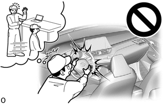
-
Be sure to read Precaution thoroughly before servicing.
-
Click hereVehicle Interior>SUPPLEMENTAL RESTRAINT SYSTEMS>AIRBAG SYSTEM>PRECAUTION
- NOTICE:
-
After turning the ignition switch off, waiting time may be required before disconnecting the cable from the negative (-) battery terminal. Therefore, make sure to read the disconnecting the cable from the negative (-) battery terminal notices before proceeding with work.
-
Click hereGeneral>INTRODUCTION>REPAIR INSTRUCTION>PRECAUTION
2.DISCONNECT CABLE FROM NEGATIVE BATTERY TERMINAL
for 8NR-FTS:
for 3ZR-FAE:
- CAUTION:
- ·
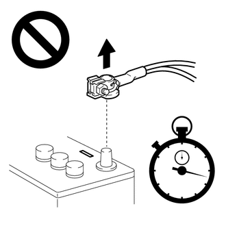
Wait at least 90 seconds after disconnecting the cable from the negative (-) battery terminal to disable the SRS system.
·If an SRS part is accidentally deployed, it may cause a serious injury.
- NOTICE:
-
When disconnecting the cable, some systems need to be initialized after the cable is reconnected.
-
Click hereGeneral>INTRODUCTION>REPAIR INSTRUCTION>INITIALIZATION
45130
3.REMOVE HORN BUTTON ASSEMBLY
- CAUTION:
-
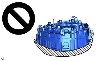 0,0 0,0 false

Deployment Side
-
When storing the horn button assembly, keep the airbag deployment side facing upward.
Check that the ignition switch off.
Check that the cable is disconnected from the negative (-) battery terminal.
- CAUTION:
-
-
Wait at least 90 seconds after disconnecting the cable from the negative (-) battery terminal to disable the SRS system.
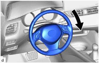
Turn the steering wheel assembly 180° to the right.
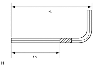
| *a | 55 mm (2.17 in.) |
| *b | 95 mm (3.74 in.) |
|
|
Protective Tape |
Wrap protective tape around a 6 mm hexagon wrench as shown in the illustration.
- HINT:
-
Use a 6 mm hexagon wrench with a long arm length of approximately 95 mm (3.74 in.) or a Phillips (+) screwdriver with a shank length of approximately 75 mm (2.95 in.).
Insert the 6 mm hexagon wrench into the service hole until the protective tape is at the position shown in the illustration, and push down the housing tab to disengage the hook.
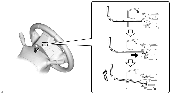
| *a | Housing Tab | *b | Hook |
|
|
Protective Tape | - | - |
- HINT:
- ·
Make sure to insert the 6 mm hexagon wrench into the service hole on the backside of the steering wheel assembly.
·Insert the 6 mm hexagon wrench parallel to the steering column.
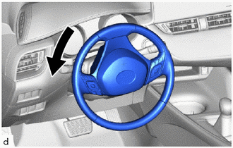
Turn the steering wheel assembly 90° to the left.
Insert the 6 mm hexagon wrench into the service hole until the protective tape is at the position shown in the illustration, and push down the housing tab to disengage the hook (1).
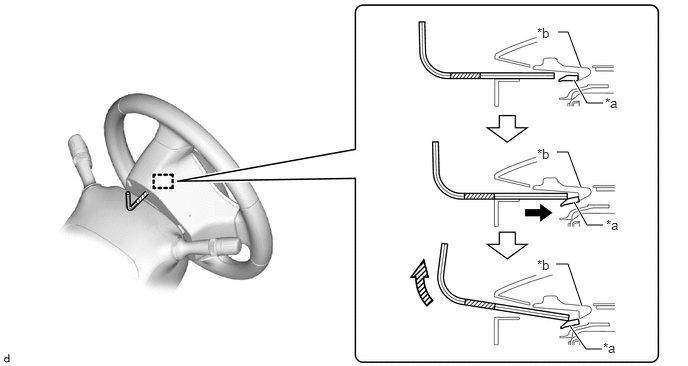
| *a | Housing Tab | *b | Hook (1) |
|
|
Protective Tape | - | - |
- HINT:
- ·
Make sure to insert the 6 mm hexagon wrench into the service hole on the backside of the steering wheel assembly.
·Insert the 6 mm hexagon wrench parallel to the steering column.
After using the 6 mm hexagon wrench to disengage the hook (1), push down the housing tab further to disengage the hook (2) as shown in the illustration.
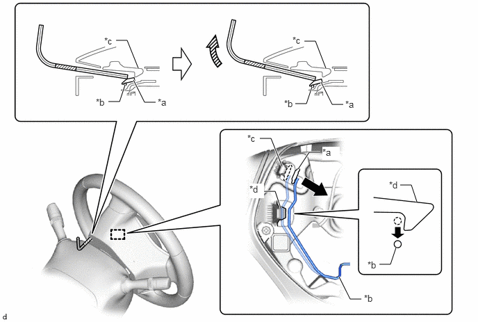
| *a | Housing Tab | *b | Omega Spring |
| *c | Hook (1) | *d | Hook (2) |
- HINT:
- ·
Pushing down the housing tab will push the omega spring and disengage it from the hook (2).
·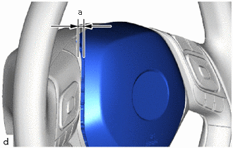 1.156,0.104 1.313,0.302 0.156,0.198 10 false a
a 10 mm
When the hook (2) has been disengaged, the horn button assembly will rise up approximately 10 mm.
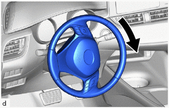
Turn the steering wheel assembly 180° to the right.
Insert the 6 mm hexagon wrench into the service hole until the protective tape is at the position shown in the illustration, and push down the housing tab to disengage the hook (1).
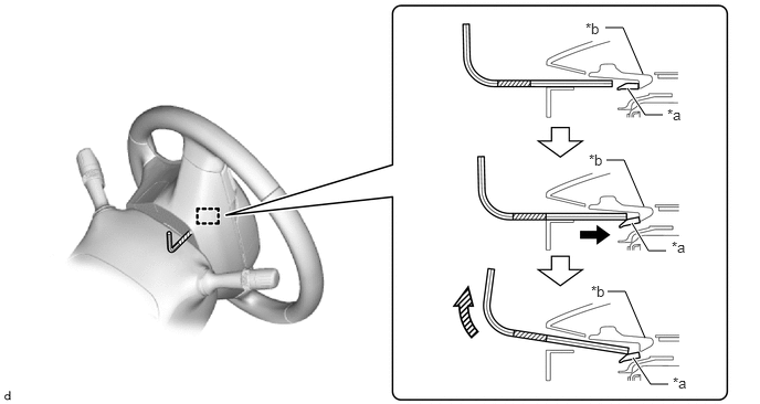
| *a | Housing Tab | *b | Hook (1) |
|
|
Protective Tape | - | - |
- HINT:
- ·
Make sure to insert the 6 mm hexagon wrench into the service hole on the backside of the steering wheel assembly.
·Insert the 6 mm hexagon wrench parallel to the steering column.
After using the 6 mm hexagon wrench to disengage the hook (1), push down the housing tab further to disengage the hook (2) as shown in the illustration.
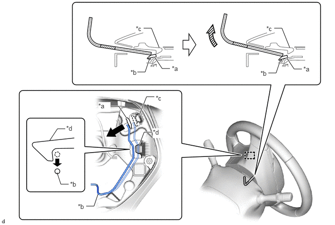
| *a | Housing Tab | *b | Omega Spring |
| *c | Hook (1) | *d | Hook (2) |
- NOTICE:
-
Lightly hold the horn button assembly so that it does not fall.
- HINT:
- ·
Pushing down the housing tab will push the omega spring and disengage it from the hook (2).
·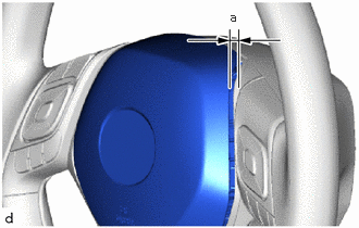 2.208,0.094 2.365,0.292 0.156,0.198 10 false a
a 10 mm
When the hook (2) has been disengaged, the horn button assembly will rise up approximately 10 mm.
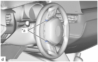
| *a | Spring |
Check that each hook is disengaged.
- HINT:
-
If a hook is disengaged, the spring will be visible at the location shown in the illustration.
Turn the steering wheel assembly 180° to the left to align the front wheels facing straight ahead.
- NOTICE:
-
Do not drop the horn button assembly.
Pull out the horn button assembly from the steering wheel assembly and hold the horn button assembly with one hand.
- NOTICE:
-
When separating the horn button assembly, do not pull the airbag wire harness.
for Single Type:
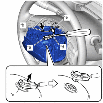
| *a | Airbag Connector |
| *b | Horn Connector |
| *c | Airbag Connector Lock |
| *d | Protective Tape |
| *e | Wire Harness Clamp |
Disconnect the horn connector from the horn button assembly.
Using a screwdriver with its tip wrapped in protective tape, release the airbag connector lock.
Disconnect the airbag connector.
Disengage the wire harness clamp to remove the horn button assembly
- NOTICE:
-
When disconnecting any airbag connector, take care not to damage the airbag wire harness.
for Dual Type:
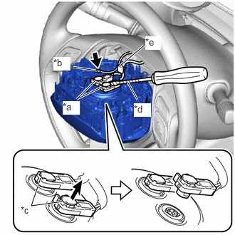
| *a | Airbag Connector |
| *b | Horn Connector |
| *c | Airbag Connector Lock |
| *d | Protective Tape |
| *e | Wire Harness Clamp |
Disconnect the horn connector from the horn button assembly.
Using a screwdriver with its tip wrapped in protective tape, release the 2 airbag connector locks.
Disconnect the 2 airbag connectors.
Disengage the wire harness clamp to remove the horn button assembly
- NOTICE:
-
When disconnecting any airbag connector, take care not to damage the airbag wire harness.