8NR-FTS ENGINE CONTROL CAMSHAFT OIL CONTROL VALVE(for Exhaust Side) REMOVAL
CAUTION / NOTICE / HINT
The necessary procedures (adjustment, calibration, initialization, or registration) that must be performed after parts are removed, installed, or replaced during the camshaft timing exhaust gear assembly removal/installation are shown below.
| Replacement Part or Procedure | Necessary Procedure | Effect/Inoperative when not Performed | Link |
|---|---|---|---|
| Replacement of camshaft timing exhaust gear assembly | Inspection After Repair | ·
Poor idle, etc. ·
Engine start function, etc. |
( ) |
PROCEDURE

 1.REMOVE FRONT WHEEL RH
51443C
2.REMOVE REAR ENGINE UNDER COVER RH
15370
3.REMOVE CAMSHAFT TIMING OIL CONTROL SOLENOID ASSEMBLY (for Exhaust Side)
4.SET NO. 1 CYLINDER TO TDC/COMPRESSION
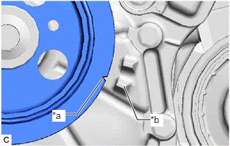
| *a | Timing Mark (Cutout) |
| *b | Protrusion |
Turn the crankshaft pulley clockwise until its timing mark (cutout) is aligned with the protrusion on the timing chain cover assembly as shown in the illustration.
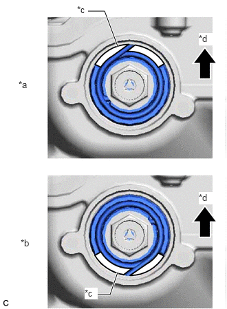
| *a | Correct |
| *b | Incorrect |
| *c | Cutout |
| *d | Up |
Check that the cutout of the camshaft timing gear assembly is at the top.
- HINT:
-
If the cutout of the camshaft timing gear assembly is not at the top, turn the crankshaft 360° clockwise and align the timing mark (cutout) of the crankshaft pulley with the protrusion on the timing chain cover assembly again.
13523F
5.REMOVE CAMSHAFT TIMING GEAR BOLT
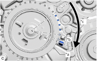
| *a | Tooth |
| *b | 10° |
| *c | 60 +/- 20° |
Turn the crankshaft pulley clockwise approximately 60° (+/- 20°).
- HINT:
-
The crankshaft pulley can be turned approximately 60° by turning it until 6 teeth of the sensor rotor have passed.
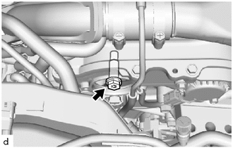
While holding the crankshaft pulley, remove the camshaft timing gear bolt.
- NOTICE:
- ·
If the camshaft timing gear bolt has been struck or dropped, replace it.
·Do not turn the crankshaft pulley after removing the camshaft timing gear bolt.