8NR-FTS ENGINE CONTROL CAMSHAFT POSITION SENSOR INSTALLATION
PROCEDURE

 11401M
1.INSTALL CAMSHAFT POSITION SENSOR (for Exhaust Side)
Connect the camshaft position sensor connector to install the camshaft position sensor to the sensor wire.
Apply a light coat of engine oil to the O-ring of the camshaft position sensor.
- NOTICE:
-
If reusing the camshaft position sensor, be sure to inspect the O-ring.
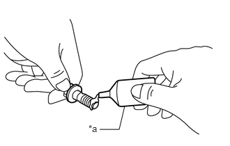
| *a | Adhesive |
Apply adhesive to 2 or 3 threads of a new bolt.
- Adhesive:
Toyota Genuine Adhesive 1324, Three Bond 1324 or equivalent
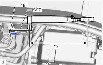
| *a | 10 mm Union Nut Wrench |
| *b | Torque Wrench Fulcrum Length |
Using SST and a 10 mm union nut wrench, install the camshaft position sensor to the cylinder head cover sub-assembly with the bolt.
- SST
- 09961-00950
- Torque:
- Specified tightening torque : 10 N*m (102 kgf*cm, 7 ft.*lbf)
- NOTICE:
- ·
If the camshaft position sensor has been struck or dropped, replace it.
·Make sure that the O-ring is not cracked or moved out of place when installing the camshaft position sensor.
- HINT:
- ·
Calculate the torque wrench reading when changing the fulcrum length of the torque wrench.
Click hereGeneral>INTRODUCTION>REPAIR INSTRUCTION>PRECAUTION
·When using a 10 mm union nut wrench (fulcrum length of 22 mm (0.866 in.)) + SST (fulcrum length of 150 mm (5.91 in.)) + torque wrench (fulcrum length of 185 mm (7.28 in.)):
5.1 N*m (52 kgf*cm, 45 in.*lbf)
Connect the sensor wire connector.
Install the fuel vapor feed pipe to the cylinder head cover sub-assembly with the 2 bolts.
- Torque:
- 10 N*m (102 kgf*cm, 7 ft.*lbf)
Connect the fuel tube sub-assembly to the hose clamp.
17705
2.INSTALL AIR CLEANER CAP WITH AIR CLEANER HOSE
55701J
3.INSTALL OUTER COWL TOP PANEL SUB-ASSEMBLY (for LHD)
55701J
4.INSTALL OUTER COWL TOP PANEL SUB-ASSEMBLY (for RHD)
55735C
5.INSTALL COWL BODY MOUNTING REINFORCEMENT RH
55736D
6.INSTALL COWL BODY MOUNTING REINFORCEMENT LH
55735A
7.INSTALL WATER GUARD PLATE LH
55737B
8.INSTALL NO. 1 HEATER AIR DUCT SPLASH SHIELD SEAL
9.INSTALL WINDSHIELD WIPER MOTOR AND LINK
11101W
10.INSTALL CAMSHAFT POSITION SENSOR (for Intake Side)
Apply a light coat of engine oil to the O-ring of the camshaft position sensor.
- NOTICE:
-
If reusing the camshaft position sensor, be sure to inspect the O-ring.
| *a | Adhesive |
Apply adhesive to 2 or 3 threads of a new bolt.
- Adhesive:
Toyota Genuine Adhesive 1324, Three Bond 1324 or equivalent
Install the camshaft position sensor to the cylinder head cover sub-assembly with the bolt.
- Torque:
- 10 N*m (102 kgf*cm, 7 ft.*lbf)
- NOTICE:
- ·
If the camshaft position sensor has been struck or dropped, replace it.
·Make sure that the O-ring is not cracked or moved out of place when installing the camshaft position sensor.
Connect the camshaft position sensor connector.
11.INSPECT FOR ENGINE OIL LEAK