Home › Vehicle Exterior › WIPER / WASHER › WIPER AND WASHER SYSTEM › 2016.10–2019.09
RM32H0E _59 Vehicle Exterior _060316 WIPER / WASHER _0295740 WIPER AND WASHER SYSTEM J

WIPER / WASHER  WIPER AND WASHER SYSTEM  Headlight Cleaner Motor and Relay Circuit  


DESCRIPTION

for LED Headlight:

The headlight ECU sub-assembly RH controls the headlight cleaner motor and pump assembly.


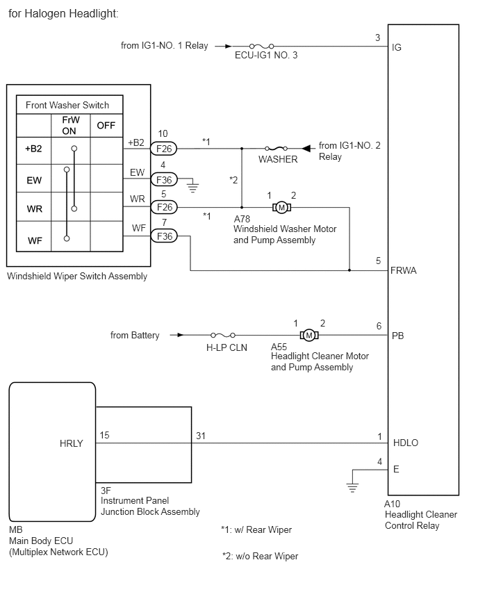
for Halogen Headlight:

The headlight cleaner control relay controls the headlight cleaner motor and pump assembly.


WIRING DIAGRAM
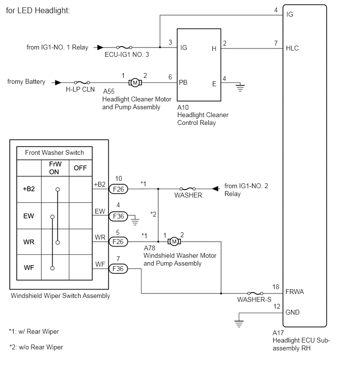
B465792E02
0.125,0.115 3.427,0.354 3.302,0.24 12 false for LED Headlight: 0.563,0.917 3.625,1.115 3.063,0.198 10 false from IG1-NO. 1 Relay 0.156,1.646 1.052,2.104 0.896,0.458 10 false fromy Battery 1.396,1.813 2.146,2.167 0.75,0.354 10 false H-LP CLN 2.219,1.073 3.427,1.427 1.208,0.354 10 false ECU-IG1 NO. 3 2.167,2.021 3.667,2.594 1.5,0.573 10 false Headlight Cleaner Motor and Pump Assembly 2.188,1.854 2.646,2.052 0.458,0.198 10 false A55 2.573,1.521 2.729,1.719 0.156,0.198 10 false 1 3.042,1.521 3.198,1.719 0.156,0.198 10 false 2 3.573,1.552 3.729,1.75 0.156,0.198 10 false 6 3.573,0.813 3.729,1.01 0.156,0.198 10 false 3 4.729,0.833 4.885,1.031 0.156,0.198 10 false 2 4.719,1.583 4.875,1.781 0.156,0.198 10 false 4 5.813,0.125 5.969,0.323 0.156,0.198 10 false 4 5.813,0.833 5.969,1.031 0.156,0.198 10 false 7 4.49,0.948 4.656,1.135 0.167,0.188 10 false H 4.5,1.698 4.667,1.885 0.167,0.188 10 false E 3.792,1.667 4.271,1.865 0.479,0.198 10 false PB 3.823,0.927 4.302,1.125 0.479,0.198 10 false IG 6.073,0.219 6.552,0.417 0.479,0.198 10 false IG 6.063,0.938 6.542,1.135 0.479,0.198 10 false HLC 6.052,6.115 6.531,6.313 0.479,0.198 10 false FRWA 6.052,6.552 6.531,6.75 0.479,0.198 10 false GND 3.76,2.198 4.219,2.396 0.458,0.198 10 false A10 3.76,2.354 4.948,2.885 1.188,0.531 10 false Headlight Cleaner Control Relay 5.771,6.01 6.073,6.229 0.302,0.219 10 false 18 5.792,6.427 6.083,6.625 0.292,0.198 10 false 12 5.031,6.281 5.896,6.635 0.865,0.354 10 false WASHER-S 3.052,5.188 3.51,5.385 0.458,0.198 10 false A78 3.042,5.344 4.646,5.833 1.604,0.49 10 false Windshield Washer Motor and Pump Assembly 3.458,4.917 3.615,5.115 0.156,0.198 10 false 1 3.823,4.906 3.979,5.104 0.156,0.198 10 false 2 3.698,4.063 4.563,4.417 0.865,0.354 10 false WASHER 5.781,6.99 6.24,7.188 0.458,0.198 10 false A17 5.781,7.146 7.083,7.625 1.302,0.479 10 false Headlight ECU Sub-assembly RH 2.385,5.625 2.844,5.823 0.458,0.198 10 false F36 2.396,4.51 2.854,4.708 0.458,0.198 10 false F36 2.396,3.938 2.854,4.135 0.458,0.198 10 false F26 2.385,5.052 2.844,5.25 0.458,0.198 10 false F26 2.469,4.271 2.625,4.469 0.156,0.198 10 false 4 2.458,4.854 2.615,5.052 0.156,0.198 10 false 5 2.469,5.417 2.625,5.615 0.156,0.198 10 false 7 2.438,3.708 2.635,3.906 0.198,0.198 10 false 10 1.99,3.833 2.469,4.031 0.479,0.198 10 false +B2 2.01,4.406 2.49,4.604 0.479,0.198 10 false EW 2.01,4.958 2.49,5.156 0.479,0.198 10 false WR 2.021,5.531 2.5,5.729 0.479,0.198 10 false WF 0.229,6.198 2.531,6.604 2.302,0.406 10 false Windshield Wiper Switch Assembly 3,4.927 3.156,5.125 0.156,0.198 10 false *1 2.979,3.823 3.135,4.021 0.156,0.198 10 false *1 3.188,4.469 3.344,4.667 0.156,0.198 10 false *2 0.188,6.958 2.49,7.365 2.302,0.406 10 false *1: w/ Rear Wiper 0.198,7.292 2.5,7.698 2.302,0.406 10 false *2: w/o Rear Wiper 4.76,3.865 5.917,4.344 1.156,0.479 10 false from IG1-NO. 2 Relay 0.531,3.156 3.438,3.354 2.906,0.198 10 false Front Washer Switch

B466956E02
0.135,8.021 1.688,8.646 1.552,0.625 10 false Main Body ECU (Multiplex Network ECU) 1.51,7.271 1.823,7.469 0.313,0.198 10 false 3F 5.76,7.469 6.073,7.667 0.313,0.198 10 false A10 4.063,5.115 4.375,5.313 0.313,0.198 10 false A55 3.51,3.198 3.823,3.396 0.313,0.198 10 false A78 0.135,7.854 0.448,8.052 0.313,0.198 10 false MB 1.51,7.417 3.063,8.042 1.552,0.625 10 false Instrument Panel Junction Block Assembly 5.771,7.625 6.927,8.458 1.156,0.833 10 false Headlight Cleaner Control Relay 4.063,5.25 5.521,6.031 1.458,0.781 10 false Headlight Cleaner Motor and Pump Assembly 3.094,5.125 3.854,5.396 0.76,0.271 10 false H-LP CLN 1.656,4.938 3.302,5.354 1.646,0.417 10 false from Battery 0.896,6.563 1.656,6.833 0.76,0.271 10 false HRLY 5.896,6.552 6.656,6.823 0.76,0.271 10 false HDLO 5.896,6.948 6.656,7.219 0.76,0.271 10 false E 5.875,4.948 6.635,5.219 0.76,0.271 10 false PB 5.656,6.833 6.417,7.104 0.76,0.271 10 false 4 5.656,6.458 6.417,6.729 0.76,0.271 10 false 1 1.49,6.438 2.25,6.708 0.76,0.271 10 false 15 2.938,6.448 3.698,6.719 0.76,0.271 10 false 31 4.396,4.76 5.156,5.031 0.76,0.271 10 false 1 4.802,4.76 5.563,5.031 0.76,0.271 10 false 2 5.646,4.802 6.406,5.073 0.76,0.271 10 false 6 5.635,3.823 6.396,4.094 0.76,0.271 10 false 5 5.854,3.969 6.615,4.24 0.76,0.271 10 false FRWA 4,2.844 4.76,3.115 0.76,0.271 10 false 1 4.365,2.844 5.125,3.115 0.76,0.271 10 false 2 3.5,3.344 5.104,4.073 1.604,0.729 10 false Windshield Washer Motor and Pump Assembly 0.104,4.052 2.344,4.49 2.24,0.438 10 false Windshield Wiper Switch Assembly 1.979,3.333 2.292,3.531 0.313,0.198 10 false WF 1.948,2.896 2.26,3.094 0.313,0.198 10 false WR 1.948,2.5 2.26,2.698 0.313,0.198 10 false EW 1.917,2.052 2.229,2.25 0.313,0.198 10 false +B2 2.354,3.458 2.667,3.656 0.313,0.198 10 false F36 2.354,3.021 2.667,3.219 0.313,0.198 10 false F26 2.344,2.615 2.656,2.813 0.313,0.198 10 false F36 2.344,2.146 2.656,2.344 0.313,0.198 10 false F26 2.427,3.25 3.188,3.521 0.76,0.271 10 false 7 2.417,2.823 3.177,3.094 0.76,0.271 10 false 5 2.406,2.385 3.167,2.677 0.76,0.292 10 false 4 2.365,1.917 3.125,2.208 0.76,0.292 10 false 10 3.875,2.302 4.635,2.573 0.76,0.271 10 false WASHER 4.781,2.094 5.76,2.781 0.979,0.688 10 false from IG1-NO. 2 Relay 5.875,0.625 6.635,0.896 0.76,0.271 10 false IG 3.521,0.74 4.75,1.115 1.229,0.375 10 false ECU-IG1 NO. 3 1.813,0.594 3.458,1.01 1.646,0.417 10 false from IG1-NO. 1 Relay 0.125,0.094 1.771,0.51 1.646,0.417 12 false for Halogen Headlight: 5.625,0.479 6.385,0.75 0.76,0.271 10 false 3 3.031,2.042 3.792,2.313 0.76,0.271 10 false *1 3.042,3.156 3.802,3.427 0.76,0.271 10 false *1 3.438,2.615 4.198,2.885 0.76,0.271 10 false *2 3.313,7.854 4.635,8.146 1.323,0.292 10 false *1: w/ Rear Wiper 3.333,8.25 4.656,8.542 1.323,0.292 10 false *2: w/o Rear Wiper 0.385,1.49 3.292,1.688 2.906,0.198 10 false Front Washer Switch

CAUTION / NOTICE / HINT

NOTICE:
·

First check that the front washer operates normally.

·

Inspect the fuses and relays for circuits related to this system before performing the following inspection procedure.


PROCEDURE

1.CHECK HEADLIGHT TYPE
a.

Check the headlight type.


Result:
Result Proceed to
for LED Headlight A
for Halogen Headlight B


A

2.READ VALUE USING GTS

B

10.CHECK HARNESS AND CONNECTOR (WINDSHIELD WIPER SWITCH ASSEMBLY - HEADLIGHT CLEANER CONTROL RELAY)
2.READ VALUE USING GTS
a.

Read the Data List according to the display on the GTS.

Click hereVehicle Exterior>WIPER / WASHER>WIPER AND WASHER SYSTEM>DATA LIST / ACTIVE TEST

Body Electrical > HL AutoLeveling > Data List
Tester Display Measurement Item Range Normal Condition Diagnostic Note
Front Window Washer Switch Washer switch condition ON/OFF ON: Windshield wiper switch assembly (front washer switch) on
OFF: Windshield wiper switch assembly (front washer switch) off
-
Body Electrical > HL AutoLeveling > Data List
Tester Display
Front Window Washer Switch
50003 361 1
OK:

On the GTS screen, ON or OFF is displayed accordingly.


Result:
Proceed to
OK
NG


OK

3.INSPECT HEADLIGHT CLEANER CONTROL RELAY

NG

7.CHECK HARNESS AND CONNECTOR (HEADLIGHT ECU SUB-ASSEMBLY RH - WINDSHIELD WIPER SWITCH ASSEMBLY)
3.INSPECT HEADLIGHT CLEANER CONTROL RELAY
a.

Disconnect the A10 headlight cleaner control relay connector.


b.

Inspect the headlight cleaner control relay.

Click hereVehicle Exterior>WIPER / WASHER>HEADLIGHT CLEANER CONTROL RELAY>ON-VEHICLE INSPECTION


Result:
Proceed to
OK
NG


OK

4.CHECK HARNESS AND CONNECTOR (HEADLIGHT CLEANER CONTROL RELAY - BATTERY AND BODY GROUND)

NG

REPLACE HEADLIGHT CLEANER CONTROL RELAY

4.CHECK HARNESS AND CONNECTOR (HEADLIGHT CLEANER CONTROL RELAY - BATTERY AND BODY GROUND)
a.
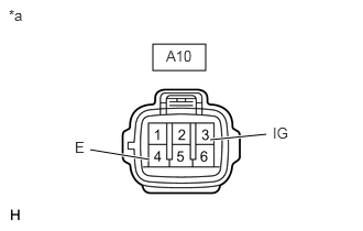
E139345C10
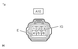
1.448,0.417 1.948,0.667 0.5,0.25 1.99,1.323 2.521,1.271 true 0.854,1.417 1.417,1.51 true 0.083,0.063 0.396,0.219 0.313,0.156 10 false *a 1.573,0.448 1.917,0.635 0.344,0.188 10 false A10 2.583,1.177 2.896,1.375 0.313,0.198 10 false IG 0.708,1.313 0.865,1.51 0.156,0.198 10 false E
*a Front view of wire harness connector
(to Headlight Cleaner Control Relay)


Disconnect the headlight cleaner control relay connector.


b.

Measure the voltage according to the value(s) in the table below.

Standard Voltage:
Tester Connection Switch Condition Specified Condition
A10-3 (IG) - Body ground Ignition switch ON 11 to 14 V


c.

Measure the resistance according to the value(s) in the table below.

Standard Resistance:
Tester Connection Switch Condition Specified Condition
A10-4 (E) - Body ground Always Below 1 Ω


Result:
Proceed to
OK
NG


OK

5.CHECK HARNESS AND CONNECTOR (HEADLIGHT CLEANER MOTOR AND PUMP ASSEMBLY CIRCUIT)

NG

REPAIR OR REPLACE HARNESS OR CONNECTOR

5.CHECK HARNESS AND CONNECTOR (HEADLIGHT CLEANER MOTOR AND PUMP ASSEMBLY CIRCUIT)
a.
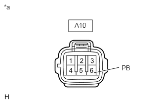
E139345C12
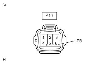
1.448,0.417 1.948,0.667 0.5,0.25 1.979,1.531 2.51,1.417 true 0.083,0.063 0.396,0.219 0.313,0.156 10 false *a 1.573,0.448 1.917,0.635 0.344,0.188 10 false A10 2.563,1.344 2.875,1.542 0.313,0.198 10 false PB
*a Front view of wire harness connector
(to Headlight Cleaner Control Relay)


Disconnect the headlight cleaner control relay connector.


b.

Using a service wire, connect A10-6 (PB) and body ground.

NOTICE:

Do not forcibly insert the service wire into the terminals of the connector when connecting a service wire.


c.

Check the headlight cleaner motor and pump assembly operate.

OK:

Headlight cleaner motor and pump assembly operate.


Result:
Proceed to
OK
NG


OK

6.CHECK HARNESS AND CONNECTOR (HEADLIGHT CLEANER CONTROL RELAY - HEADLIGHT ECU SUB-ASSEMBLY RH)

NG

8.CHECK HARNESS AND CONNECTOR (HEADLIGHT CLEANER MOTOR AND PUMP ASSEMBLY - BATTERY)
6.CHECK HARNESS AND CONNECTOR (HEADLIGHT CLEANER CONTROL RELAY - HEADLIGHT ECU SUB-ASSEMBLY RH)
a.

Disconnect the A10 headlight cleaner control relay connector.


b.

Disconnect the A17 headlight ECU sub-assembly RH connector.


c.

Measure the resistance according to the value(s) in the table below.

Standard Resistance:
Tester Connection Condition Specified Condition
A10-2 (H) - A17-7 (HLC) Always Below 1 Ω
A10-2 (H) or A17-7 (HLC) - Body ground Always 10 kΩ or higher


Result:
Proceed to
OK
NG


OK

REPLACE HEADLIGHT ECU SUB-ASSEMBLY RH

NG

REPAIR OR REPLACE HARNESS OR CONNECTOR

7.CHECK HARNESS AND CONNECTOR (HEADLIGHT ECU SUB-ASSEMBLY RH - WINDSHIELD WIPER SWITCH ASSEMBLY)
a.

Disconnect the A17 headlight ECU sub-assembly RH connector.


b.

Disconnect the F36 windshield wiper switch assembly connector.


c.

Measure the resistance according to the value(s) in the table below.

Standard Resistance:
Tester Connection Condition Specified Condition
A17-18 (FRWA) - F36-7 (WF) Always Below 1 Ω
A17-18 (FRWA) or F36-7 (WF) - Body ground Always 10 kΩ or higher


Result:
Proceed to
OK
NG


OK

REPLACE HEADLIGHT ECU SUB-ASSEMBLY RH

NG

REPAIR OR REPLACE HARNESS OR CONNECTOR

8.CHECK HARNESS AND CONNECTOR (HEADLIGHT CLEANER MOTOR AND PUMP ASSEMBLY - BATTERY)
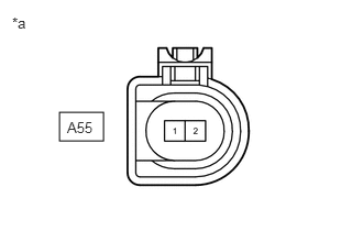
a.
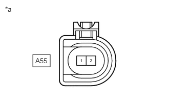
B462687C03
0.667,1.115 1.021,1.365 0.354,0.25 0.719,1.156 1.177,1.354 0.458,0.198 10 false A55 0.104,0.104 0.417,0.302 0.313,0.198 10 false *a
*a Front view of wire harness connector
(to Headlight Cleaner Motor and Pump Assembly)


Disconnect the headlight cleaner motor and pump assembly connector.


b.

Measure the voltage according to the value(s) in the table below.

Standard Voltage:
Tester Connection Condition Specified Condition
A55-1 - Body ground Always 11 to 14 V


Result:
Proceed to
OK
NG


OK

9.CHECK HARNESS AND CONNECTOR (HEADLIGHT CLEANER MOTOR AND PUMP ASSEMBLY - HEADLIGHT CLEANER CONTROL RELAY)

NG

REPAIR OR REPLACE HARNESS OR CONNECTOR

9.CHECK HARNESS AND CONNECTOR (HEADLIGHT CLEANER MOTOR AND PUMP ASSEMBLY - HEADLIGHT CLEANER CONTROL RELAY)
a.

Disconnect the A55 headlight cleaner motor and pump assembly connector.


b.

Disconnect the A10 headlight cleaner control relay connector.


c.

Measure the resistance according to the value(s) in the table below.

Standard Resistance:
Tester Connection Condition Specified Condition
A55-2 - A10-6 (PB) Always Below 1 Ω
A55-2 or A10-6 (PB) - Body ground Always 10 kΩ or higher


Result:
Proceed to
OK
NG


OK

REPLACE HEADLIGHT CLEANER MOTOR AND PUMP ASSEMBLY

NG

REPAIR OR REPLACE HARNESS OR CONNECTOR

10.CHECK HARNESS AND CONNECTOR (WINDSHIELD WIPER SWITCH ASSEMBLY - HEADLIGHT CLEANER CONTROL RELAY)
E139345C16
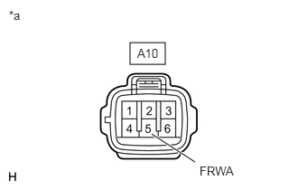
1.5,0.49 1.906,0.74 0.406,0.25 1.75,1.542 2.25,1.865 true 2.302,1.885 2.917,2.083 0.615,0.198 10 false FRWA 1.583,0.531 2.042,0.729 0.458,0.198 10 false A10 0.104,0.094 0.417,0.292 0.313,0.198 10 false *a
*a Front view of wire harness connector
(to Headlight Cleaner Control Relay)


a.

Disconnect the headlight cleaner control relay connector.


b.

Measure the voltage according to the value(s) in the table below.

Standard Voltage:
Tester Connection Condition Specified Condition
A10-5 (FRWA) - Body ground Ignition switch ON, front washer switch off 11 to 14 V
Ignition switch ON, front washer switch on Below 1 V


Result:
Proceed to
OK
NG


OK

11.CHECK HARNESS AND CONNECTOR (HEADLIGHT CLEANER CONTROL RELAY - IG CIRCUIT AND BODY GROUND)

NG

REPAIR OR REPLACE HARNESS OR CONNECTOR

11.CHECK HARNESS AND CONNECTOR (HEADLIGHT CLEANER CONTROL RELAY - IG CIRCUIT AND BODY GROUND)
a.
E139345C17
1.479,0.385 1.906,0.625 0.427,0.24 1.99,1.313 2.573,1.177 true 0.875,1.365 1.438,1.531 true 2.635,1.104 2.948,1.302 0.313,0.198 10 false IG 0.74,1.271 0.896,1.469 0.156,0.198 10 false E 1.563,0.427 2.021,0.625 0.458,0.198 10 false A10 0.115,0.115 0.375,0.323 0.26,0.208 10 false *a
*a Front view of wire harness connector
(to Headlight Cleaner Control Relay)


Disconnect the headlight cleaner control relay connector.


b.

Measure the voltage according to the value(s) in the table below.

Standard Voltage:
Tester Connection Condition Specified Condition
A10-3 (IG) - Body ground Ignition switch ON 11 to 14 V


c.

Measure the resistance according to the value(s) in the table below.

Standard Resistance:
Tester Connection Condition Specified Condition
A10-4 (E) - Body ground Always Below 1 Ω


Result:
Proceed to
OK
NG


OK

12.CHECK HARNESS AND CONNECTOR (HEADLIGHT CLEANER MOTOR AND PUMP ASSEMBLY CIRCUIT)

NG

REPAIR OR REPLACE HARNESS OR CONNECTOR

12.CHECK HARNESS AND CONNECTOR (HEADLIGHT CLEANER MOTOR AND PUMP ASSEMBLY CIRCUIT)
a.
E139345C13
1.448,0.417 1.948,0.667 0.5,0.25 2,1.521 2.573,1.396 true 0.083,0.063 0.396,0.219 0.313,0.156 10 false *a 1.573,0.448 1.917,0.635 0.344,0.188 10 false A10 2.635,1.313 2.948,1.51 0.313,0.198 10 false PB
*a Front view of wire harness connector
(to Headlight Cleaner Control Relay)


Disconnect the headlight cleaner control relay connector.


b.

Using a service wire, connect A10-6 (PB) and body ground.

NOTICE:

Do not forcibly insert the service wire into the terminals of the connector when connecting a service wire.


c.

Check the headlight cleaner motor and pump assembly operate.

OK:

Headlight cleaner motor and pump assembly operate.


Result:
Proceed to
OK
NG


OK

13.CHECK HARNESS AND CONNECTOR (INSTRUMENT PANEL JUNCTION BLOCK ASSEMBLY - HEADLIGHT CLEANER CONTROL RELAY)

NG

17.CHECK HARNESS AND CONNECTOR (HEADLIGHT CLEANER MOTOR AND PUMP ASSEMBLY - BATTERY)
13.CHECK HARNESS AND CONNECTOR (INSTRUMENT PANEL JUNCTION BLOCK ASSEMBLY - HEADLIGHT CLEANER CONTROL RELAY)
a.

Measure the voltage according to the value(s) in the table below.

Standard Voltage:
Tester Connection Condition Specified Condition
3F-31 - Body ground Light control switch in head position Below 1 V
Light control switch off 4.2 V or higher


Result:
Proceed to
OK
NG


OK

REPLACE HEADLIGHT CLEANER CONTROL RELAY

NG

14.CHECK HARNESS AND CONNECTOR (INSTRUMENT PANEL JUNCTION BLOCK ASSEMBLY - HEADLIGHT CLEANER CONTROL RELAY)
a.

Disconnect the 3F instrument panel junction block assembly connector.


b.

Disconnect the A10 headlight cleaner control relay connector.


c.

Measure the resistance according to the value(s) in the table below.

Standard Resistance:
Tester Connection Condition Specified Condition
3F-31 - A10-1 (HDLO) Always Below 1 Ω
3F-31 or A10-1 (HDLO) - Body ground Always 10 kΩ or higher


Result:
Proceed to
OK
NG


OK

15.INSPECT INSTRUMENT PANEL JUNCTION BLOCK ASSEMBLY

NG

REPAIR OR REPLACE HARNESS OR CONNECTOR

15.INSPECT INSTRUMENT PANEL JUNCTION BLOCK ASSEMBLY
a.
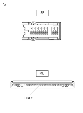
E358486C01
1.5,0.417 2,0.667 0.5,0.25 1.5,2.917 2,3.167 0.5,0.25 1.219,3.938 1.635,3.521 true 0.115,0.094 0.427,0.25 0.313,0.156 10 false *a 1.677,0.438 1.99,0.594 0.313,0.156 10 false 3F 1.635,2.948 1.948,3.104 0.313,0.156 10 false MB 1.01,3.969 1.469,4.146 0.458,0.177 10 false HRLY
*a Component without harness connected
(Instrument Panel Junction Block Assembly)


Remove the instrument panel junction block assembly.


b.

Remove the main body ECU (multiplex network body ECU).


c.

Measure the resistance according to the value(s) in the table below.

Standard Resistance:
Tester Connection Condition Specified Condition
3F-31 - MB-15 (HRLY) Always Below 1 Ω
3F-31 - Body ground Always 10 kΩ or higher


Result:
Proceed to
OK
NG


OK

16.REPLACE HEADLIGHT CLEANER CONTROL RELAY

NG

REPLACE INSTRUMENT PANEL JUNCTION BLOCK ASSEMBLY

16.REPLACE HEADLIGHT CLEANER CONTROL RELAY
a.

Replace the headlight cleaner control relay assembly with a new or a known good one.

Click hereVehicle Exterior>WIPER / WASHER>HEADLIGHT CLEANER CONTROL RELAY>REMOVAL


Result:
Result Proceed to
The operation of the headlight cleaner returns to normal. A
The operation of the headlight cleaner does not return to normal. (for LHD) B
The operation of the headlight cleaner does not return to normal. (for RHD) C


A

END (HEADLIGHT CLEANER CONTROL RELAY WAS DEFECTIVE)

B

REPLACE MAIN BODY ECU (MULTIPLEX NETWORK BODY ECU)

C

REPLACE MAIN BODY ECU (MULTIPLEX NETWORK BODY ECU)

17.CHECK HARNESS AND CONNECTOR (HEADLIGHT CLEANER MOTOR AND PUMP ASSEMBLY - BATTERY)
a.
B462687C04
0.563,1.063 0.979,1.333 0.417,0.271 0.635,1.125 1.094,1.323 0.458,0.198 10 false A55 0.115,0.135 0.427,0.333 0.313,0.198 10 false *a
*a Front view of wire harness connector
(to Headlight Cleaner Motor and Pump Assembly)


Disconnect the headlight cleaner motor and pump assembly connector.


b.

Measure the voltage according to the value(s) in the table below.

Standard Voltage:
Tester Connection Condition Specified Condition
A55-1 - Body ground Always 11 to 14 V


Result:
Proceed to
OK
NG


OK

18.CHECK HARNESS AND CONNECTOR (HEADLIGHT CLEANER MOTOR AND PUMP ASSEMBLY - HEADLIGHT CLEANER CONTROL RELAY)

NG

REPAIR OR REPLACE HARNESS OR CONNECTOR

18.CHECK HARNESS AND CONNECTOR (HEADLIGHT CLEANER MOTOR AND PUMP ASSEMBLY - HEADLIGHT CLEANER CONTROL RELAY)
a.

Disconnect the A55 headlight cleaner motor and pump assembly connector.


b.

Disconnect the A10 headlight cleaner control relay connector.


c.

Measure the resistance according to the value(s) in the table below.

Standard Resistance:
Tester Connection Condition Specified Condition
A55-2 - A10-6 (PB) Always Below 1 Ω
A55-2 or A10-6 (PB) - Body ground Always 10 kΩ or higher


Result:
Proceed to
OK
NG


OK

REPLACE HEADLIGHT CLEANER MOTOR AND PUMP ASSEMBLY

NG

REPAIR OR REPLACE HARNESS OR CONNECTOR