BRAKE SYSTEM (OTHER) BRAKE BOOSTER(for LHD) REMOVAL
CAUTION / NOTICE / HINT
The necessary procedures (adjustment, calibration, initialization, or registration) that must be performed after parts are removed, installed, or replaced during the brake booster assembly removal/installation are shown below.
| Replacement Part or Procedure | Necessary Procedure | Effect/Inoperative when not Performed | Link |
|---|---|---|---|
| Disconnect cable from negative battery terminal | Memorize steering angle neutral point | Lane departure alert system (w/ Steering Control) | ( ) |
| Simple intelligent parking assist system*1 | |||
| Toyota parking assist-sensor system (w/ Simple Intelligent Parking Assist System)*1 | |||
| Pre-collision system | |||
| Initialize back door lock | Power door lock control system | ()
|
|
| Drive the vehicle until stop and start control is permitted (approximately 5 to 60 minutes)*2 | Stop and start system | ()
|
*1: When performing learning using the GTS.
*2: w/ Stop and start system
PROCEDURE

 87211
1.REMOVE NO. 1 AIR DUCT
47201
2.REMOVE BRAKE MASTER CYLINDER SUB-ASSEMBLY
47101A
3.REMOVE BRAKE PEDAL RETURN SPRING
4.LOOSEN CLEVIS LOCK NUT
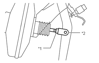
| *1 | Clevis Lock Nut |
| *2 | Brake Master Cylinder Push Rod Clevis |
Loosen the clevis lock nut of the brake master cylinder push rod clevis.
47264A
5.REMOVE PUSH ROD PIN
51441
6.REMOVE NO. 1 ENGINE UNDER COVER
55225
7.REMOVE DASH PANEL HEAT INSULATOR
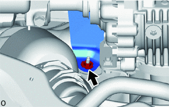
Remove the nut.
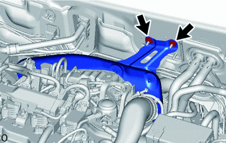
Remove the 2 nuts and the dash panel heat insulator.
8.DISCONNECT CHECK VALVE TO CONNECTOR TUBE HOSE
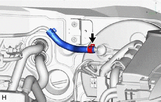
Slide the clip and disconnect the check valve to connector tube hose from the brake booster assembly.
44610
9.REMOVE BRAKE BOOSTER ASSEMBLY
w/ Stop and Start System:
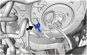
Disconnect the connector from the vacuum sensor assembly.
w/ Vacuum Warning Switch:
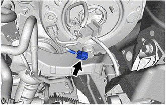
Disconnect the vacuum warning switch connector.
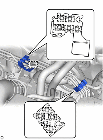
Disengage the 5 camps to remove the No. 1 brake tube clamp from the brake tubes.
Disengage the 5 clamps to separate the No. 2 brake tube clamps from the brake tubes.
Disengage the clamp to remove the No. 2 brake tube clamp from the vehicle body.
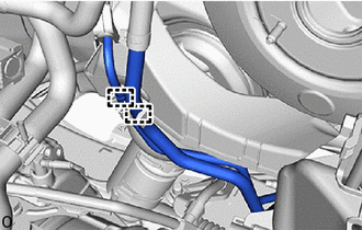
Disengage the 2 clamps to separate the fuel pipe from the fuel pipe clamp.
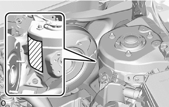

|
Protective Tape |
Apply protective tape around the vehicle body.
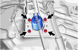
Remove the 4 nuts and push the brake booster assembly toward the engine compartment.
- NOTICE:
-
Do not apply excessive force to the brake lines.
Remove the brake master cylinder push rod clevis and lock nut from the brake booster assembly.
Remove the brake booster assembly from the vehicle body.
- NOTICE:
-
Do not apply excessive force to the brake lines or refrigerant lines.
44785
10.REMOVE BRAKE BOOSTER GASKET
Remove the brake booster gasket from the brake booster assembly.