HEATING / AIR CONDITIONING AIR CONDITIONING SYSTEM(for Automatic Air Conditioning System with Side-mounted Air Conditioner Pressure Sensor) B1451 Compressor Solenoid Circuit
DESCRIPTION
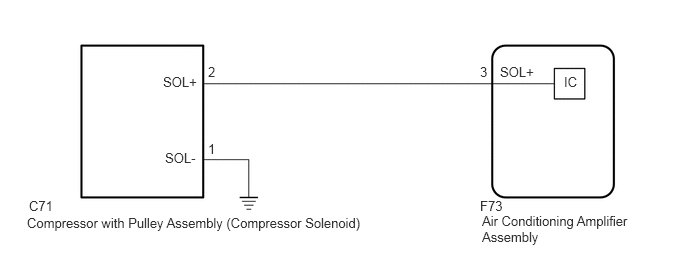
In this circuit, the cooler compressor assembly (compressor solenoid) receives a refrigerant compression demand signal from the air conditioning amplifier assembly.
Based on this signal, the cooler compressor assembly (compressor solenoid) changes the amount of compressor output.
| DTC No. | Detection Item | DTC Detection Condition | Trouble Area | Memory |
|---|---|---|---|---|
| B1451 | Compressor Solenoid Circuit | Any of the following conditions is met:
·
Open in compressor solenoid circuit ·
Short in compressor solenoid circuit |
·
Compressor with pulley assembly (compressor solenoid) ·
Harness or connector between air conditioning amplifier assembly and compressor with pulley assembly (compressor solenoid) ·
Air conditioning amplifier assembly |
- |
| Vehicle Condition | |||
|---|---|---|---|
| Pattern 1 | Pattern 2 | ||
| Diagnosis Condition | Ignition switch ON | ○ | ○ |
| Malfunction Status | Open in compressor solenoid circuit | ○ | - |
| Short in compressor solenoid circuit | - | ○ | |
| Detection Time | 30 seconds or more | 30 seconds or more | |
| Number of Trips | 1 trip | 1 trip | |
- HINT:
-
The air conditioning amplifier assembly stores this DTC if the malfunction has occurred for the period of time indicated in the brackets.
WIRING DIAGRAM
PROCEDURE
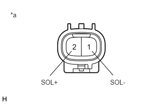
| *a | Component without harness connected
(Cooler Compressor Assembly (Compressor Solenoid)) |
Disconnect the C71 cooler compressor assembly (compressor solenoid) connector.
Measure the resistance according to the value(s) in the table below.
- Standard Resistance:
Tester Connection Condition Specified Condition 1 (SOL-) - 2 (SOL+) 25°C (77°F) 10.1 to 11.1 Ω
- Result:
Proceed to OK NG
OK
NG
Measure the resistance according to the value(s) in the table below.
- Standard Resistance:
Tester Connection Condition Specified Condition C71-1 (SOL-) - Body ground Always Below 1 Ω
- Result:
Proceed to OK NG
OK
NG
Disconnect the F73 air conditioning amplifier assembly connector.
Measure the resistance according to the value(s) in the table below.
- Standard Resistance:
Tester Connection Condition Specified Condition C71-2 (SOL+) - F73-3 (SOL+) Always Below 1 Ω C71-2 (SOL+) or F73-3 (SOL+) - Body ground Always 10 kΩ or higher
- Result:
Result Proceed to NG A OK (When troubleshooting according to the Problem Symptoms Table) B OK (When troubleshooting according to the DTC) C
A
B
C
Clear the DTCs.
- Body Electrical > Air Conditioner > Clear DTCs
- 50002 121
Check for DTCs.
- Body Electrical > Air Conditioner > Trouble Codes
- 50001 121
- Result:
Result Proceed to DTCs are not output A DTCs are output B
A
Click hereGeneral>INTRODUCTION>HOW TO TROUBLESHOOT ECU CONTROLLED SYSTEMS>HOW TO PROCEED WITH TROUBLESHOOTING
B